
Scintillator materials based on lanthanide silicates or lanthanide phosphates, and related methods and articles

a technology of lanthanide silicates and scintillator materials, applied in the field of materials for detecting high energy radiation, i, can solve the problems of low light yield, inability to produce large-size, high-quality single crystals, and many other problems

Inactive Publication Date: 2009-06-11
GENERAL ELECTRIC CO
View PDF14 Cites 10 Cited by
  • Summary
  • Abstract
  • Description
  • Claims
  • Application Information

AI Technical Summary

Benefits of technology

[0017]A method for detecting high-energy radiation with a scintillation detector cons

Problems solved by technology

However, many of them also have some drawbacks.
The common problems are low light yield, physical weakness, and the inability to produce large-size, high quality single crystals.
For example, the thallium-activated materials are very hygroscopic, and can also produce a large and persistent after-glow, which can interfere with scintillator function.
Moreover, the BGO materials frequently have a slow decay time.
On the other hand, the LSO materials are expensive, and may also contain radioactive lutetium isotopes which can also interfere with scintillator function.

Method used


Image

  • Scintillator materials based on lanthanide silicates or lanthanide phosphates, and related methods and articles
  • Scintillator materials based on lanthanide silicates or lanthanide phosphates, and related methods and articles
  • Scintillator materials based on lanthanide silicates or lanthanide phosphates, and related methods and articles

Examples


example 1

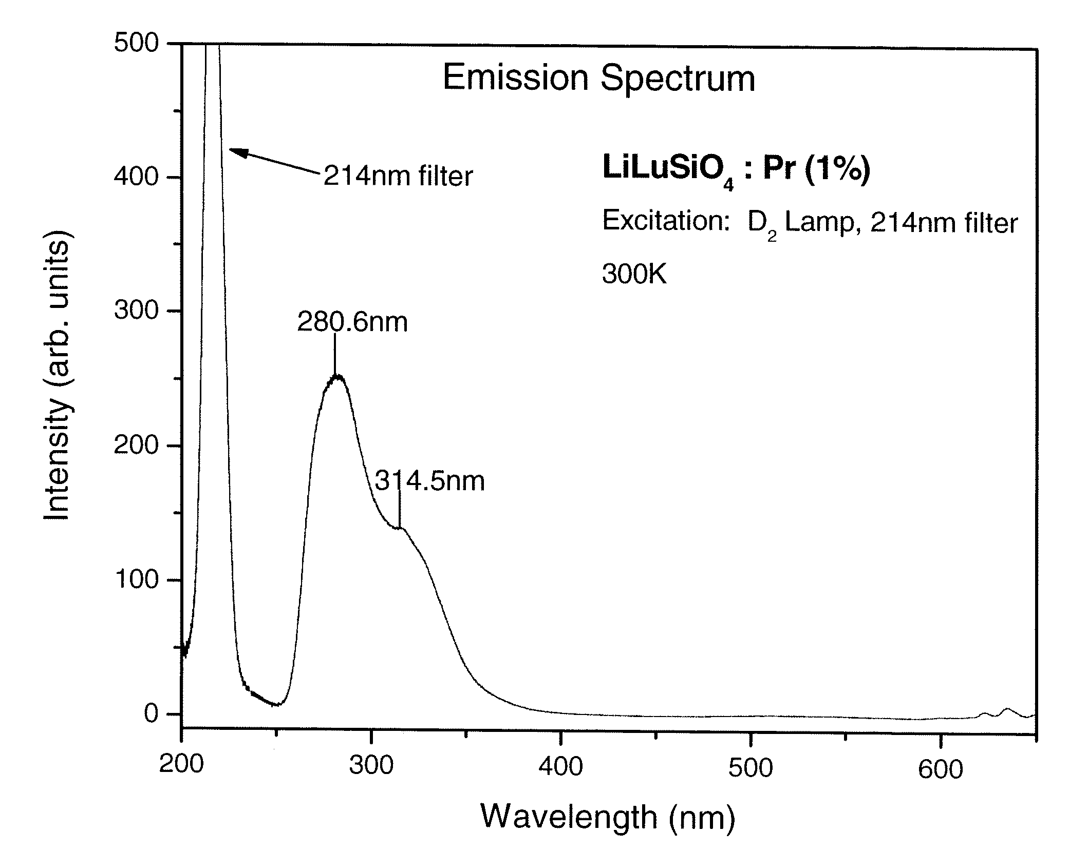
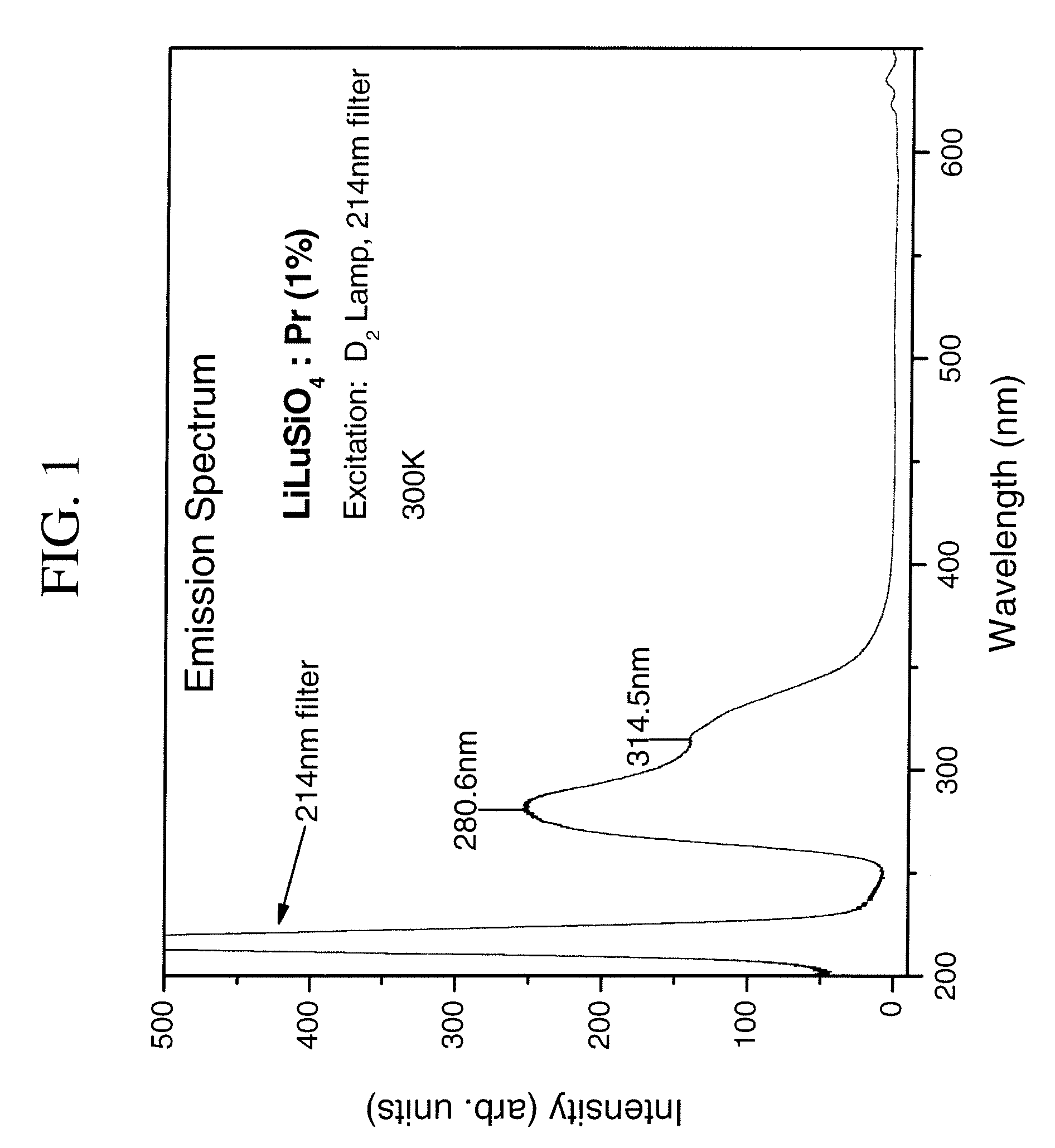
[0048]A set of samples of a praseodymium-activated scintillator composition was prepared in this example. The matrix portion of the composition had the formula LiLuSiO4, while the level of praseodymium activator was varied (1%, 2%, 5%, and 10%). An illustrative preparation is described, for 5 grams of LiLu0.99Pr0.01SiO4. In this preparation, 0.7426 grams of Li2CO3 (10 mole % excess), 3.5990 grams of Lu2O3, 0.0311 grams of Pr6O11, and 1.2522 grams of silicic acid were mixed with 2 mole % LiF (flux). The mixture was heated to 800° C. for two hours in a slightly-reducing atmosphere of 0.5% H2. The resulting sample was further ground and reheated at 1000° C. for five hours, under the same atmosphere. All grinding steps were carried out in air. (Component proportions were adjusted to provide the samples below). The nominal formula for each of the four compositions, after the re-heating step, was as follows:

LiLu0.99Pr0.01SiO4; (1% activator)

LiLu0.98Pr0.02SiO4; (2% activator)

LiLu0.95Pr0.05...

example 2

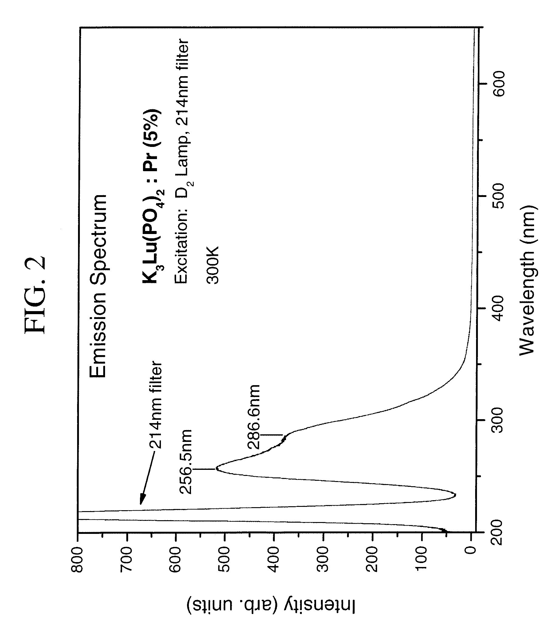
[0050]In this example, a phosphate-based scintillator material (5 grams) was prepared according to the present invention. The matrix portion of the composition had the formula K3Lu(PO4)2, while the level of praseodymium activator was 5%. In this preparation, 2.292 grams of K2CO3 (10 mole % excess), 1.9669 grams of Lu2O3, 0.0886 grams of Pr6O11, and 2.8858 grams of DAP (diammonium hydrogen phosphate; 10 mole % excess) were mixed and heated to 600° C. for two hours in air. The product was re-ground and reheated to 950° C. for five hours, in a slightly-reducing atmosphere of 0.5% H2. All of the grinding was carried out in air.

[0051]The emission spectrum for this sample was also determined under UV and X-ray excitation, using an optical spectrometer. FIG. 2 is a plot of wavelength (nm) as a function of intensity (arbitrary units) for sample. The peak emission wavelength for the sample was about 257 nm. (The peak emission may vary for each particular phosphate compound). As in the case o...


PUM


Abstract

A scintillator composition is described. The composition includes a matrix material in the form of a host lattice characterized by a 4f5d→4f optical transition under activation. The matrix material is based on certain lithium-lanthanide silicate compounds or alkali-lanthanide phosphate compounds. The composition also includes a praseodymium (Pr) activator for the matrix material. Radiation detectors which include crystal scintillators are also part of the present invention, as are methods for detecting high-energy radiation, using these devices.

Description

BACKGROUND OF THE INVENTION[0001]The invention described herein relates generally to materials for detecting high energy radiation, i.e., luminescent materials. In some specific embodiments, the invention is directed to scintillator compositions which are especially useful for detecting gamma-rays and X-rays under a variety of conditions.[0002]When high energy radiation contacts a scintillating crystal, a large number of electron-hole pairs are formed within the crystal. Recombination of these electron-hole pairs will release low levels of energy, e.g., several eV. The energy can be emitted directly from the recombination in the form of light, or can be transferred to a light-emitting ion center which then emits a specific wavelength of light. This low-energy emission can be detected by some form of light-detection means, e.g., a photodetector. The photodetector produces an electrical signal proportional to the number of light pulses received, and to their intensity.[0003]Scintillat...

Claims


Application Information

Patent Timeline
IPC IPC(8): G01T1/20
CPCG01T1/202
Inventor SRIVASTAVA, ALOK MANICOMANZO, HOLLY ANNVARTULI, JAMES SCOTT
Owner GENERAL ELECTRIC CO
Learn More