Power control apparatus and electronic appliance equipped with power control apparatus

a technology of power control apparatus and power control device, which is applied in the direction of electric variable regulation, process and machine control, instruments, etc., can solve the problems of increasing power consumption, wasting global resources, and users having to pay extra for electricity bills, so as to reduce the size and cost of a power supply apparatus, reduce the number of mounted components, and reduce the space in the height direction

Inactive Publication Date: 2009-06-11
SONY CORP
View PDF19 Cites 20 Cited by
  • Summary
  • Abstract
  • Description
  • Claims
  • Application Information

AI Technical Summary

Benefits of technology

[0037]According to an embodiment of the present invention, since a construction is used where dielectrics that form a row of capacitors, where a DC removing capacitor and a variable capacitor are serially connected, are integrally laminated, an effect is obtained that it is possible to reduce the size and the cost of a power supply apparatus.
[0038]Thereby, an effect is obtained that it is possible to reduced the number of mounted components of a power supply apparatus and to reduce the space in the height direction.
[0039]Further, an effect is obtained that it is also possible to control AC power with little power loss and low noise.

Problems solved by technology

As described above, power loss in electronic appliances and electronic circuits not only increases power consumption, causing users to pay extra for their electricity bill, but also wastes global resources and leads to increased global warming.
The drop in voltage in this case is a DC voltage drop that is fundamentally all converted to heat, which results in a large loss in power.
The drop in voltage that is required is greatly affected by fluctuations in the characteristics of components aside from the power supply transformer, the size of the load current, and the like, and if a margin is set for the voltage drop so as to stabilize the operation of the electronic appliance, the power loss in the normal state will be extremely large.
However, the efficiency will change depending on the input and load conditions, with efficiency deteriorating under light load conditions and the like.
S62-259417 has a small capacitance and needs a high control voltage, which makes it impractical.

Method used


Image

  • Power control apparatus and electronic appliance equipped with power control apparatus
  • Power control apparatus and electronic appliance equipped with power control apparatus
  • Power control apparatus and electronic appliance equipped with power control apparatus

Examples


Embodiment Construction

[0054]Preferred embodiments of the present invention will now be described with reference to FIGS. 3A, 3B to 14A, 14B.

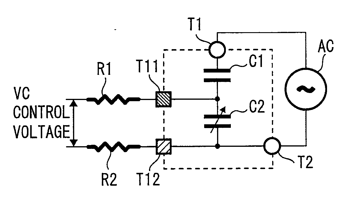
[0055]The detailed circuit construction and multilayer state of a power control apparatus according to an embodiment of the present invention will now be described so as to cover every construction of a variable capacitance device with a four-terminal construction.

[0056]In particular, this variable capacitance device is characterized by having a variable capacitor and a DC removing capacitor integrally laminated. As specific examples, this variable capacitance device can have a two-element construction, a three-element construction, or a four-element construction. In addition, with the two-element and the three-element constructions, the capacitance can be expanded. Both the variable capacitance and the fixed capacitance can be expanded by connecting further capacitors in parallel.

[0057]It is possible to produce a single component by integrally laminating a DC removi...


PUM


Abstract

A power control apparatus includes an input terminal and an output terminal for an AC signal; a DC removing capacitor connected between the input terminal and the output terminal; and a variable capacitor that is connected between the input terminal and the output terminal and whose capacitance can be changed by a control signal. One of a current and a voltage of the AC signal is controlled by changing the capacitance of the variable capacitor using the control signal, and dielectrics that form a serially connected row of capacitors composed of the DC removing capacitor and the variable capacitor are configured so as to be integrally laminated, and the control signal is applied across a dielectric that forms the variable capacitor and the AC signal is applied across the dielectrics that form the row of capacitors.

Description

CROSS REFERENCES TO RELATED APPLICATIONS[0001]The present invention contains subject matter related to Japanese Patent Application JP 2007-315215 filed in the Japanese Patent Office on Dec. 5, 2007, the entire contents of which being incorporated herein by reference.BACKGROUND OF THE INVENTION[0002]1. Field of the Invention[0003]The present invention relates to an electronic appliance and a power control apparatus favorably applied to controlling voltage or current in an electronic appliance.[0004]2. Description of the Related Art[0005]In recent years, electronic technology has come to be appreciated for its convenience and efficiency, and the spread of electronic appliances such as IT (information technology) and AV(audio visual) devices has accelerated on a global scale. At the same time, there has been increasing attention on the limited nature of the global environment and global resources, which has led to strong demand for low-energy technology in appliances.[0006]For example,...

Claims


Application Information

Patent Timeline
Patent Type & Authority Applications(United States)
IPC IPC(8): H02J3/00
CPCH02M5/08H02M7/05
Inventor KANNO, MASAYOSHI
Owner SONY CORP
Why Eureka
Try Eureka