Laminated rotor core and method for manufacturing the same

a technology of rotor core and laminated rotor core, which is applied in the direction of manufacturing stator/rotor body, magnetic circuit rotating parts, magnetic circuit shape/form/construction, etc., can solve the problems of low method productivity, reduced product quality, and complicated manufacturing operation, and achieves the effect of convenient blanking operation

Inactive Publication Date: 2009-06-11
MITSUI HIGH TEC INC
View PDF13 Cites 20 Cited by
  • Summary
  • Abstract
  • Description
  • Claims
  • Application Information

AI Technical Summary

Benefits of technology

[0022]According to the method for manufacturing a laminated rotor core of the second invention, it is preferable that in the annular shape forming step, the plurality of band-shaped core sheets are oriented in tangential directions at different angles with respect to the laminated rotor core being formed in an annular shape. Such a configuration allows sheet winding load to be

Problems solved by technology

Thus, the method is low in productivity.
According to the art disclosed in the publication, however, the integration of the superposed band-shaped core sheets 72, 73 requires, e.g., welding, which makes the manufacturing operation complicated.
Therefore, when a laminated core having a small diameter is produced according to the method, winding of the sheets is diffi

Method used


Image

  • Laminated rotor core and method for manufacturing the same
  • Laminated rotor core and method for manufacturing the same
  • Laminated rotor core and method for manufacturing the same

Examples


first embodiment

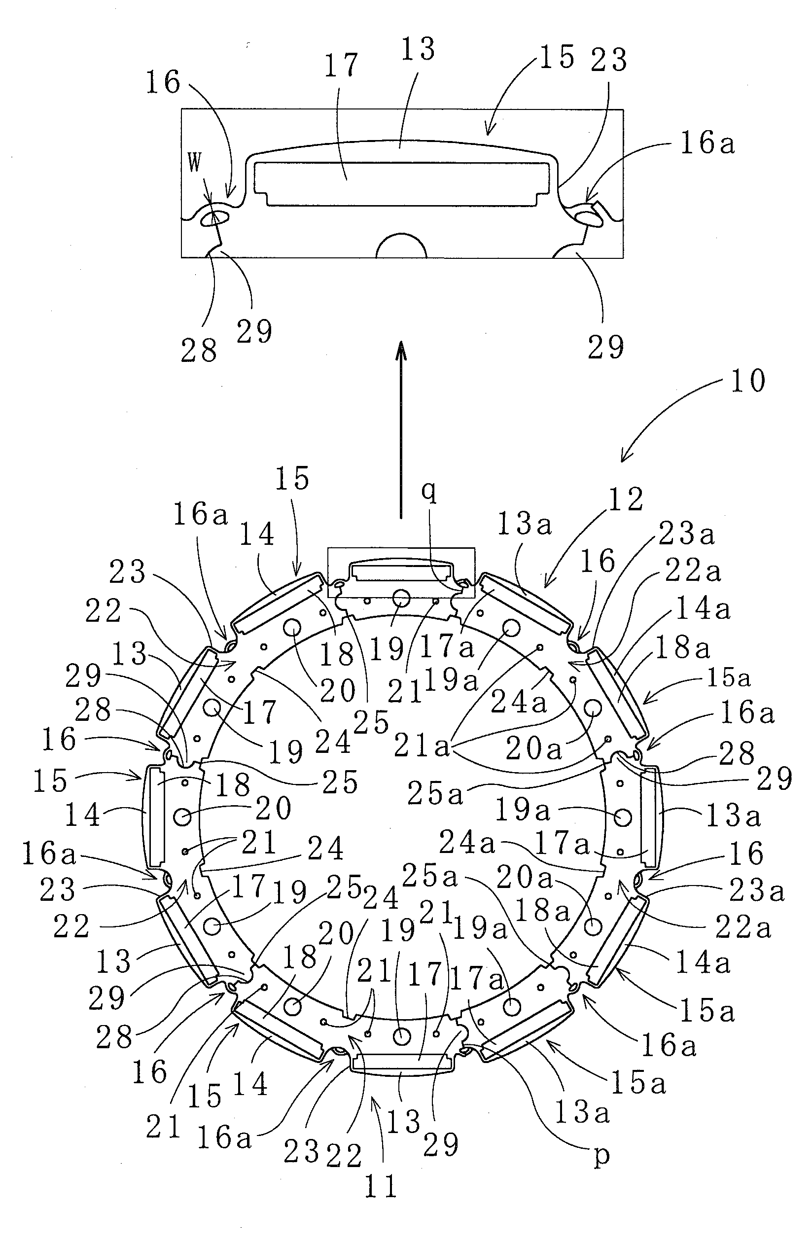
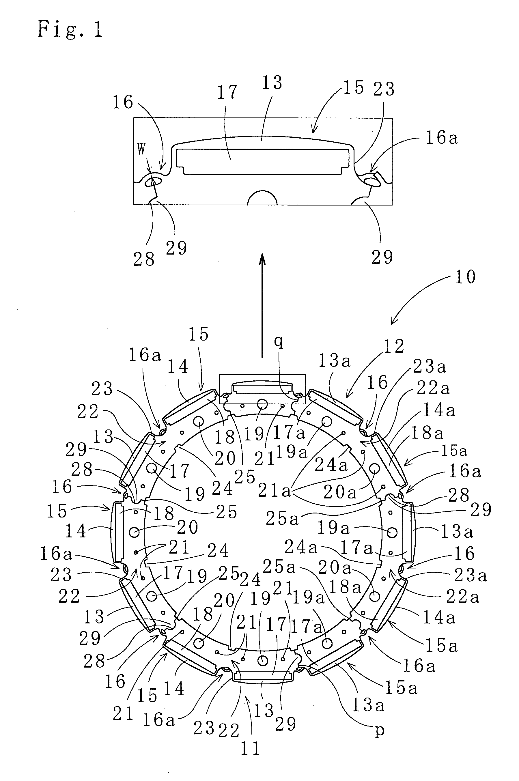
[0050]Next, a method for manufacturing a laminated rotor core according to the present invention is described with reference to FIGS. 1, 2.

[0051]First, the steel strip is blanked by a pressing machine to form the plurality of band-shaped core sheets 11, 12.

[0052]In this instance, the notch 23 is formed in the radially outward portion of the joining portion 22 between the pole sections 13, 14 of each segment core sheet 15 included in the band-shaped core sheet 11. The first engaging groove 24 is formed in the radially inward portion at the center in the circumferential direction of each segment core sheet 15, and the mutually facing cutouts to form the second engaging groove 25 are formed at the radially inward sides of the adjacent segment core sheets 15. Then, the pilot holes 19, 20 are formed in each segment core sheet 15. The band-shaped core sheet 12 is processed in the same manner. (Stamping Step)

[0053]Next, as shown in FIG. 2, the band-shaped core sheets 11, 12 are spirally wo...

second embodiment

[0064]Next, with reference to FIG. 4, a method for manufacturing a laminated rotor core according to the present invention is described.

[0065]As shown in FIG. 4, the segment core sheets 15, 15a are wound in a state that the winding phases of the band-shaped core sheets 11, 12 are shifted from each other by 180 degrees with respect to the mandrel 27. Thus, the bending moment is not applied to the mandrel 27, and the steady operation can be done. Start points of winding the band-shaped core sheets 11, 12 oriented in tangential directions at different angles (by 180 degrees) have a phase difference of 180 degrees ± an angle for one pole section pitch. And the interlocking portions 21, 21a are provided at predetermined positions in the segment core sheets 15, 15a forming the band-shaped core sheets 11, 12, respectively. These two features are common to the method according to the first embodiment of the present invention.

[0066]The present invention has been described with reference to t...


PUM

PropertyMeasurementUnit
Phase shiftaaaaaaaaaa
Angleaaaaaaaaaa
Widthaaaaaaaaaa

Abstract

A stamping step of forming a plurality of band-shaped core sheets (11), (12) having arc-shaped segment core sheets (15), (15a), the adjacent segment core sheets (15), (15a) connected together by narrow-width connecting portions (16), (16a) provided therebetween, the segment core sheets (15), (15a) having a plurality of pole sections (13), (14), (13a), (14a) protruding radially outward; and an annular shape forming step of winding the plurality of band-shaped core sheets (11), (12) in a spiral form while bending the band-shaped core sheets (11), (12) at the connecting portions (16), (16a) and superimposing the pole sections (13), (14), (13a), (14a) vertically one on another, thereby laminating the band-shaped core sheets (11), (12); wherein in the stamping step, notches (23a), (23) to be positioned in correspondence with the connecting portions (16), (16a) bent in the annular shape forming step are formed at radially outward sides of joining portions (22a), (22), the joining portions joining the adjacent pole sections (13a), (14a), (13), (14) in the segment core sheets (15a), (15) and positioned above and below the bent connecting portions (16), (16a).

Description

TECHNICAL FIELD[0001]The present invention relates to a laminated rotor core formed by effectively using a core material and applied to a motor or a generator, and a method for manufacturing the laminated rotor core.BACKGROUND ART[0002]To improve a yield of a material from which core sheets are stamped, a laminated rotor core is produced by stamping segment core sheets (also referred to as separate core sheets) in the form of divided core sheets, laminating the segment core sheets to form separate laminated cores, and subsequently assembling the separate laminated cores. Another method for producing a laminated rotor core with improved material yield involves stamping a band in predetermined shape consisting of connected segment core sheets, and spirally winding the band-shaped sheet.[0003]When the laminated rotor core is produced by winding the band-shaped core sheet, the band-shaped core sheet in a straight form is stamped from a metal sheet, i.e., a material, thereby improving th...

Claims


Application Information

Patent Timeline
IPC IPC(8): H02K21/14H02K15/03
CPCH02K1/276H02K1/30Y10T29/49012H02K15/03H02K15/026
Inventor MYOJIN, IWAO
Owner MITSUI HIGH TEC INC
Why Eureka
Try Eureka