Laser processing apparatus

a laser processing and apparatus technology, applied in the direction of hologram nature/properties, optical radiation measurement, instruments, etc., can solve the problems of low light use efficiency, high cost of laser processing apparatuses, uneven resultant shape of processed products, etc., to prevent degradation of positioning accuracy, high light use efficiency, and high positioning accuracy

Inactive Publication Date: 2009-06-11
RICOH KK
View PDF13 Cites 31 Cited by
  • Summary
  • Abstract
  • Description
  • Claims
  • Application Information

AI Technical Summary

Benefits of technology

[0015]The present invention was conceived in view of the above-described problems in the prior art, and an embodiment of the present provides a laser processing apparatus that can achieve high posit

Problems solved by technology

(a) Since the light beam is blocked by a mask, light use efficiency becomes very low depending on the pattern to be projected; and
(b) Variation in light intensity guided to the mask leads to unevenness of the resultant shape of the processed products.
However, such a laser processing apparatuses is expensive, and in addition, it causes vibration due to mechanical movement of the movable part or element.
Another problem is that when the

Method used


Image

  • Laser processing apparatus
  • Laser processing apparatus
  • Laser processing apparatus

Examples


first example

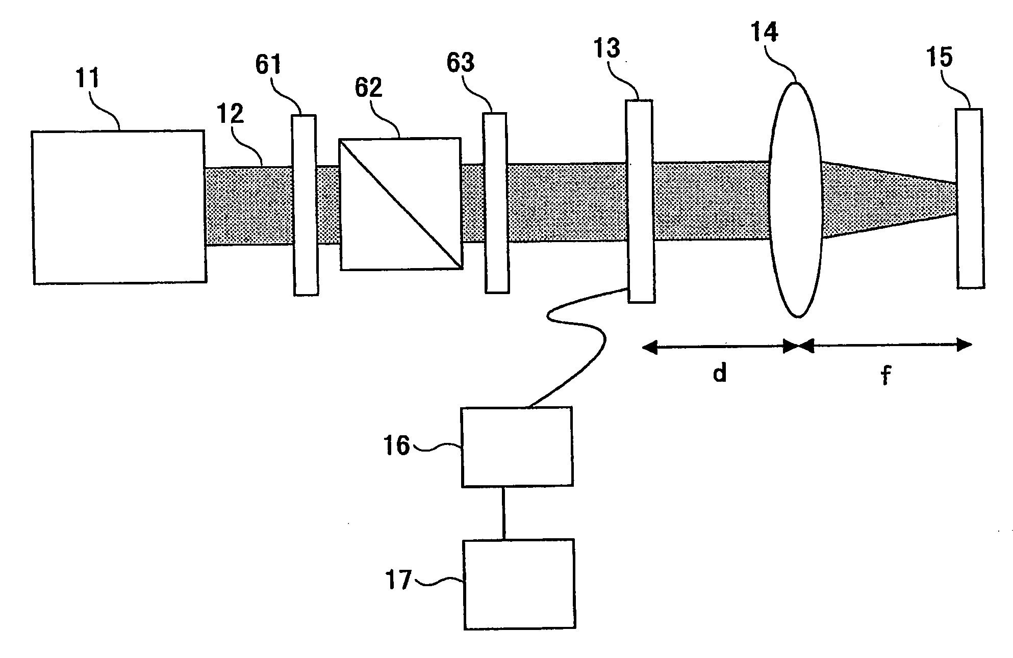
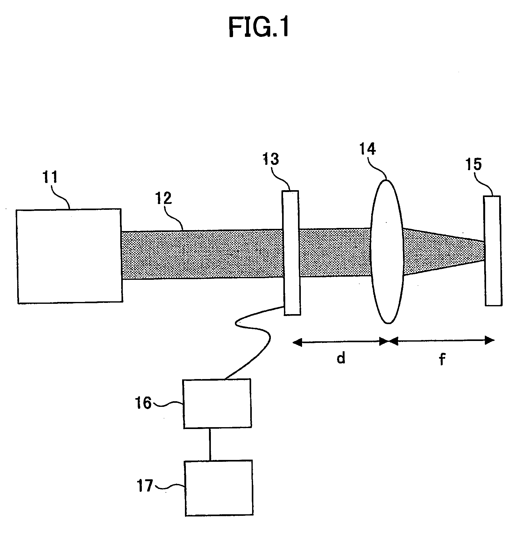
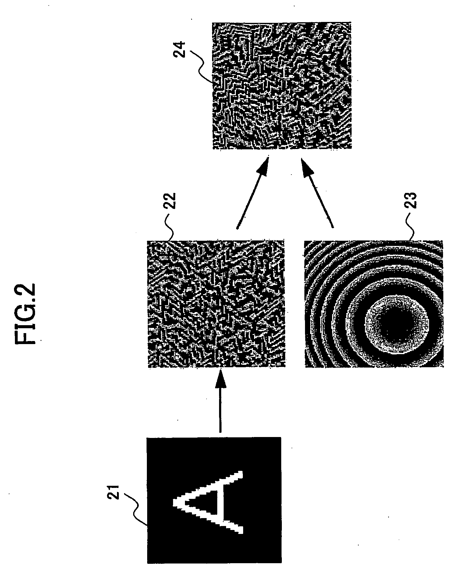
[0031]FIG. 1 is a schematic diagram of a laser processing apparatus of the first example according to an embodiment of the invention, and FIG. 2 illustrates an example of synthesis of a hologram image to be processed.

[0032]The laser processing apparatus includes a laser source 11, a spatial phase modulator 13, a focusing lens 14, a controller 16, and a computer 17. The laser beam 12 emitted from the laser source 11 is subjected to phase modulation at the spatial phase modulator 13, and guided by the focusing lens 14 onto the object 15 to be processed. The spatial phase modulator 13 is controlled by the controller 16. The computer 17 generates and supplies input data to the controller 16.

[0033]The laser source 11 is, for example, a second-harmonic 532 nm YAG laser. The focal length “f” of the focusing lens 14 is 10 mm, and the distance “d” from the spatial phase modulator 13 to the focusing lens 14 is 10 mm.

[0034]The spatial phase modulator 13 produces a phase difference making use o...

example 2

[0040]The position displacement hologram data 23 may be synthetic data defined by a combination of horizontally adjusting hologram data for controlling displacement in a direction parallel to the processed surface and vertically adjusting hologram data for controlling displacement in a direction perpendicular to the processed surface. With this arrangement, the position displacement hologram data set 23 is generated in a simpler manner. Again, “combining” the horizontal hologram data and the vertical hologram data is a process for adding these two data sets together, and if the resultant phase modulation exceeds 2π, the residual obtained by subtracting 2π from the added phase modulation is used as the input data. If phase modulation is required only in a direction perpendicular or parallel to the processed surface, the required data set is solely added.

example 3

[0041]FIG. 3 illustrates another example of synthetic hologram data used in the laser processing apparatus according to an embodiment of the invention, and FIG. 4A through FIG. 4C show examples of position displacement hologram data 33 to be combined with the computer-synthetic hologram image data.

[0042]The synthetic-hologram data 34 produced in FIG. 3 are used in a laser processing apparatus shown in FIG. 1 to adjust the laser beam spot position only in a direction parallel to the processed surface. Based on the image 31 representing a shape to be processed, computer-synthesized hologram image data 32 are calculated so as to reproduce the image 31 on the processed surface. To shift the image reproducing position along the processed surface, horizontal position displacement hologram data set 33 having a sawtooth phase distribution profile in this example is added to the hologram image data 32. The resultant synthetic data 34 are input to the spatial phase modulator 13.

[0043]If the h...


PUM

PropertyMeasurementUnit
Lengthaaaaaaaaaa
Widthaaaaaaaaaa
Phaseaaaaaaaaaa

Abstract

A laser processing apparatus includes a laser source (11), a spatial phase modulator (13) configured to modulate a phase of a laser beam emitted from the laser source, a synthetic data generator (17) configured to generate synthetic data by combining hologram image data representing a pattern image to be processed with position displacement hologram data for shifting the pattern image to a prescribed position, the synthetic data being input to the spatial phase modulator for the phase modulation of the laser beams, and a focusing optical unit (14) configured to guide the phase-modulated laser beam onto a surface to be processed to reproduce the pattern image on the processed surface.

Description

BACKGROUND OF THE INVENTION[0001]The present invention generally relates to a laser processing apparatus for processing articles using a laser beam, and more particularly, to a laser processing technique applied to fabrication of high-precision components requiring a resolution of several microns to several hundred nanometers, as well as two-dimensional or three-dimensional shape-processed devices (such as micro-electric-mechanical systems (MEMS) devices or diffractive optics) and components with a number of fine holes, such as photonic crystals, printed boards, or inkjet heads.[0002]Because a laser beam can converge accurately on a fine area in short time, it is used in various types of processing, including direct material processing and indirect processing making use of chemical change, reformation or alteration of the material. Direct processing includes surface patterning, drilling, ablation, and cutting of metals or synthetic resins. Examples of indirect processing include lit...

Claims


Application Information

Patent Timeline
IPC IPC(8): G03H1/12B23K26/00G02F1/01G03H1/04H01S3/00
CPCB23K26/0656G03H1/2286G03H1/0808G03H1/0891G03H1/2294G03H2001/0066G03H2001/0094G03H2001/048G03H2001/0484G03H2001/0491G03H2001/221G03H2001/2244G03H2001/2255G03H2222/33G03H2222/35G03H2225/32G03H2240/42G03H1/2249G03H2210/30B23K26/38B23K26/066
Inventor SEO, MANABUYAMADA, YASUFUMINORIKANE, YOSHIHIRO
Owner RICOH KK
Why Eureka
Try Eureka