Method for solving high papr problem of mcm communication system using unitary transform

a technology of multicarrier modulation and power ratio, applied in the field of multicarrier modulation system, can solve the problems of high peak-to-average power ratio of mcm system, time-domain signals of mcm system usually suffer the problem of high peak-to-average power ratio, etc., and achieve the effect of solving the problem of difficult design of such a power amplifier

Active Publication Date: 2009-06-11
NAT TAIWAN UNIV
View PDF1 Cites 87 Cited by
  • Summary
  • Abstract
  • Description
  • Claims
  • Application Information

AI Technical Summary

Benefits of technology

[0010]The method adopts the concept of SLM but avoids the conventional SLM's drawback of using a large number of IFFTs. The method therefore has a significantly less complexity in effectively reducing the PAPR or the clipping noise power resulted from a high PAPR of a MCM system without sacrificing error rate.

Problems solved by technology

However, in contrast to single-carrier modulation systems, MCM systems have an inherent disadvantage.
That is, the time-domain signals of a MCM system usually suffer the problem of high peak-to-average power ratio (PAPR).
However, the design of such a power amplifier is not an easy task.
This mode of operation would inevitably cause non-linear distortion.
As illustrated, the conventional method requires Q inverse fast Fourier transforms (IFFTs) and each IFFT requires highly complicated computation.
These all contribute to the implementation complexity of SLM.
Although the need of multiple IFFTs is eliminated, the need of multiple unitary transform matrices U still requires rather significant computation and therefore still has substantial implementation difficulty, where

Method used


Image

  • Method for solving high papr problem of mcm communication system using unitary transform
  • Method for solving high papr problem of mcm communication system using unitary transform
  • Method for solving high papr problem of mcm communication system using unitary transform

Examples


first embodiment

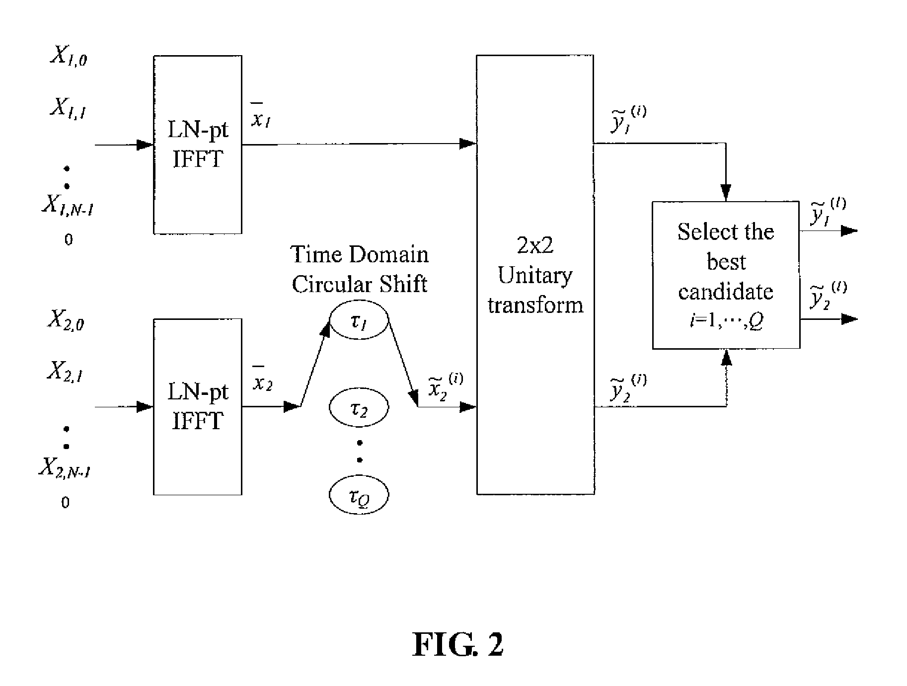
[0018]FIG. 2 is a schematic diagram showing the present invention, which performs 2×2 unitary transforms for a MCM system having N (N≧2) sub-carriers.

[0019]First in step 1, in order to achieve more accurate estimation of the PAPR, the present embodiment supplements (L-1)N zeros (L≧1) to the baseband signal blocks X1=(X1,0, X1,1, . . . , X1,N-1) and X2=(X2,0, X2,1, . . . , X2,N-1), respectively, so that X1 and X2 become (X1,0, X1,1, . . . , X1,N-1, 0, . . . ,0) and (X2,0, X2,1, . . . , X2,N-1, 0, . . . ,0).

[0020]The baseband signal blocks X1 and X2 then undergo LN-point IFFT (denoted as “LN-pt IFFT” in the drawing), respectively, to obtain L-time oversampled time-domain signal blocks x1=(x1,0, x1,1, . . . , x1,LN-1) and x2=(x2,0, x2,1, . . . , x2,LN-1).

[0021]Subsequently, in step 2, x2 undergoes Q (Q≧1) different Time Domain Circular Shift with parameters τ1, τ2, . . . , τQ (all greater than zero) respectively to obtain {tilde over (x)}2(i)=TS( x2,τi)=(a2,1(i),a2,2(i), . . . ,a2,n(i...

second embodiment

[0027]FIG. 3 is a schematic diagram showing the present invention, which performs circular shift in the frequency domain in contrast to the circular shift in the time domain performed by the previous embodiment.

[0028]Step 1 is identical to the previous embodiment and (L-1) zeros (L≧1) are supplemented to the baseband signal blocks X1=(X1,0, X1,1, . . . , X1,N-1) and X2=(X2,0, X2,1, . . . ,X2,N-1), respectively, so that X1 and X2 become (X1,0, X1,1, . . . , X1,N-1,0, . . . ,0) and (X2,0, X2,1, . . . , X2,N-1,0, . . . ,0). The baseband signal blocks X1 and X2 then undergo LN-point IFFT (denoted as “LN-pt IFFT” in the drawing), respectively, to obtain L-time oversampled time-domain signal blocks x1=(x1,0, x1,1, . . . , x1,N-1) and x2=(x2,0, x2,1, . . . , x2,LN-1).

[0029]Then, in step 2, x2 is processed by the following function for Q times sequentially:

b2,n(i)=x2,ne−j2roiki1LN,n=0,1,Λ,(LN-1),i=1, . . . ,Q

The function is equivalent to subjecting frequency-domain signal block (X2,0, X2,1...


PUM


Abstract

The method contains the following steps. First, in a MCM system with N sub-carriers, the baseband signal blocks Xj, j=1, 2, . . . ,B are supplemented with zeros and processed with LN-point IFFT, respectively, to obtain L-time oversampled time-domain signal blocks xj, j=1,2, . . . ,B. Then, xj undergoes Q Time Domain Circular Shifts or Frequency Domain Circular Shifts to obtain Q signal blocks {tilde over (x)}j(i<sub2>j< / sub2>), ij=1,Λ,Q. Subsequently, a B×B unitary transform is performed against ( x1,{tilde over (x)}2(i<sub2>2< / sub2>), . . . ,{tilde over (x)}B(i<sub2>B< / sub2>)). After the unitary transform, for each (i2, . . . ,iB) a combination having B time-domain signal blocks is obtained as follows: ({tilde over (y)}1(i<sub2>2< / sub2>, . . . ,i<sub2>B< / sub2>),{tilde over (y)}2(i<sub2>2< / sub2>, . . . ,i<sub2>B< / sub2>), . . . ,{tilde over (y)}B(i<sub2>2< / sub2>, . . . ,i<sub2>B< / sub2>)=( x1,{tilde over (x)}2(i<sub2>2< / sub2>), . . . ,{tilde over (x)}B(i<sub2>B< / sub2>)) cU where U is the B×B unitary matrix, and c is an arbitrary constant (c≠0). Finally, the total QB-1 combinations are compared against each other to select a best candidate for transmission that could produce the lowest peak value, or the smallest PAPR, or the lowest clipping noise power.

Description

BACKKGROUND OF THE INVENTION[0001]1. Field of the Invention[0002]The present invention generally relates to multicarrier modulation systems, and more particularly to a method for solving the high peak-to-average power ratio problem of the multicarrier modulation system.[0003]2. The Related Arts[0004]Multicarrier modulation (MCM) systems, such as those adopting orthogonal frequency division multiplexing (OFDM) modulation / demodulation techniques, have been widely applied in digital subscriber loop (DSL), digital video broadcasting (DVB), digital audio broadcasting (DAB), and wireless local area network (WLAN), due to their high spectral efficiency, better immunity to multi-path fading, easier equalization to frequency-selective fading channels.[0005]However, in contrast to single-carrier modulation systems, MCM systems have an inherent disadvantage. That is, the time-domain signals of a MCM system usually suffer the problem of high peak-to-average power ratio (PAPR). In a MCM system, ...

Claims


Application Information

Patent Timeline
Patent Type & Authority Applications(United States)
IPC IPC(8): H04L27/28
CPCH04L27/2615H04L27/2614
Inventor LIN, MAO-CHAODENG, SHANG-KANGCHEN, TIEN-HUILO, YU-HUNG
Owner NAT TAIWAN UNIV
Why Eureka
Try Eureka