Method for solving high PAPR problem of MCM communication system using unitary transform
What is AI technical title?
AI technical title is built by Patsnap AI team. It summarizes the technical point description of the patent document.
a technology of communication system and power ratio, applied in the field of multicarrier modulation system, can solve the problems of non-linear distortion, difficult design of such a power amplifier, inherent disadvantage of mcm system,
Active Publication Date: 2011-09-27
NAT TAIWAN UNIV
View PDF1 Cites 9 Cited by
Summary
Abstract
Description
Claims
Application Information
AI Technical Summary
This helps you quickly interpret patents by identifying the three key elements:
Problems solved by technology
Method used
Benefits of technology
Benefits of technology
The present invention provides a novel method to solve the high PAPR problem in MCM systems. The method involves supplementing the baseband signal blocks with zeros and processing them with LN-point IFFT to obtain L-time oversampled time-domain signal blocks. These blocks are then circularly shifted to obtain Q signal blocks. A B×B unitary transform is performed against the Q signal blocks, and a combination of B time-domain signal blocks is obtained for each shift. The total combinations are compared to select the best candidate for transmission with the lowest peak value or clipping noise power. The method avoids the use of a large number of IFFTs, making it more efficient in reducing PAPR and clipping noise power without sacrificing error rate.
However, the design of such a power amplifier is not an easy task.
This mode of operation would inevitably cause non-linear distortion.
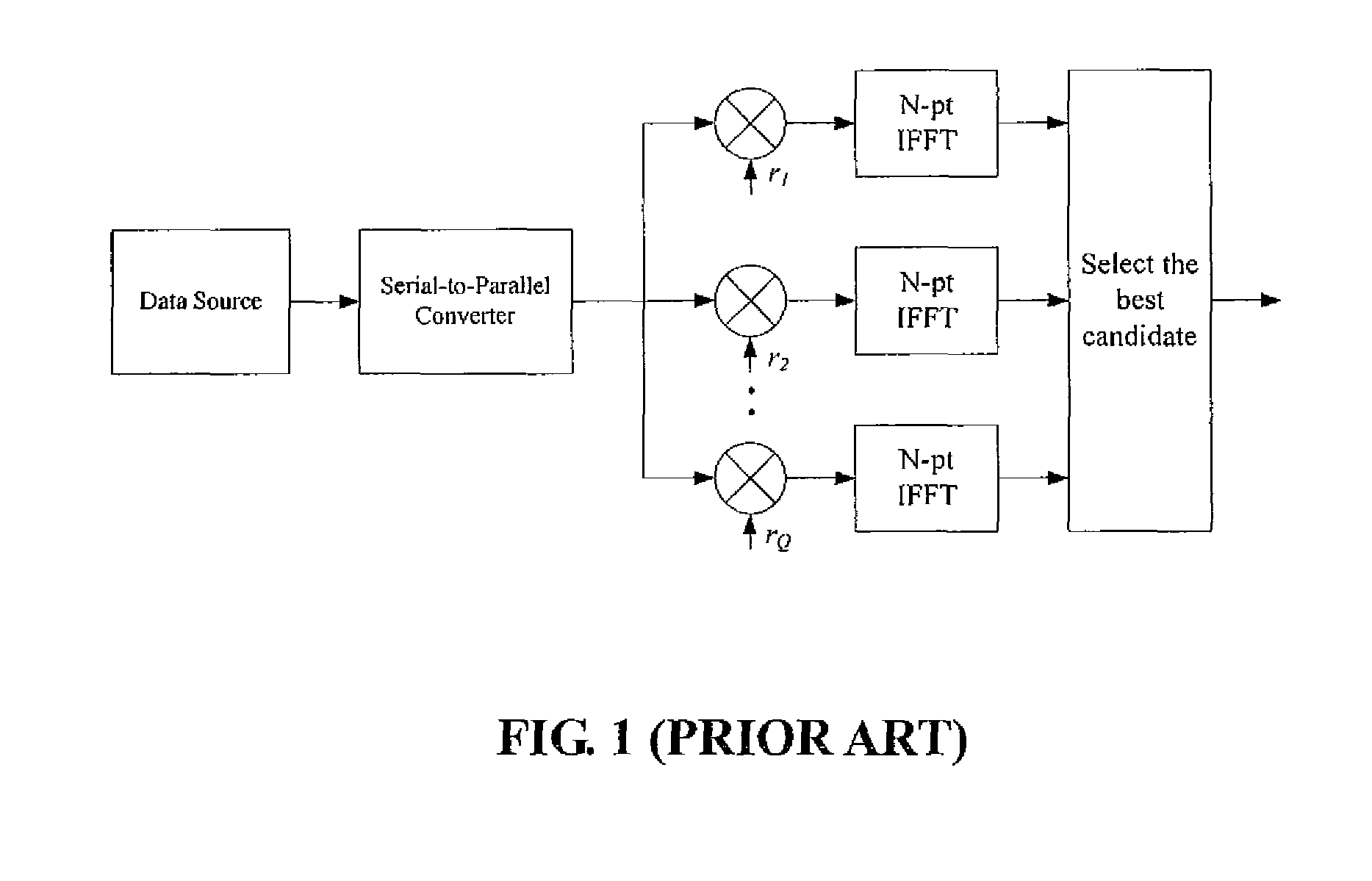
As illustrated, the conventional method requires Q inverse fast Fourier transforms (IFFTs) and each IFFT requires highly complicated computation.
These all contribute to the implementation complexity of SLM.
However, the unitary transform matrices U still requires rather significant computation and therefore still has substantial implementation difficulty, where
Method used
Image
Click on the blue label to locate the original text in one second.
Reading with bidirectional positioning of images and text.
Examples
first embodiment
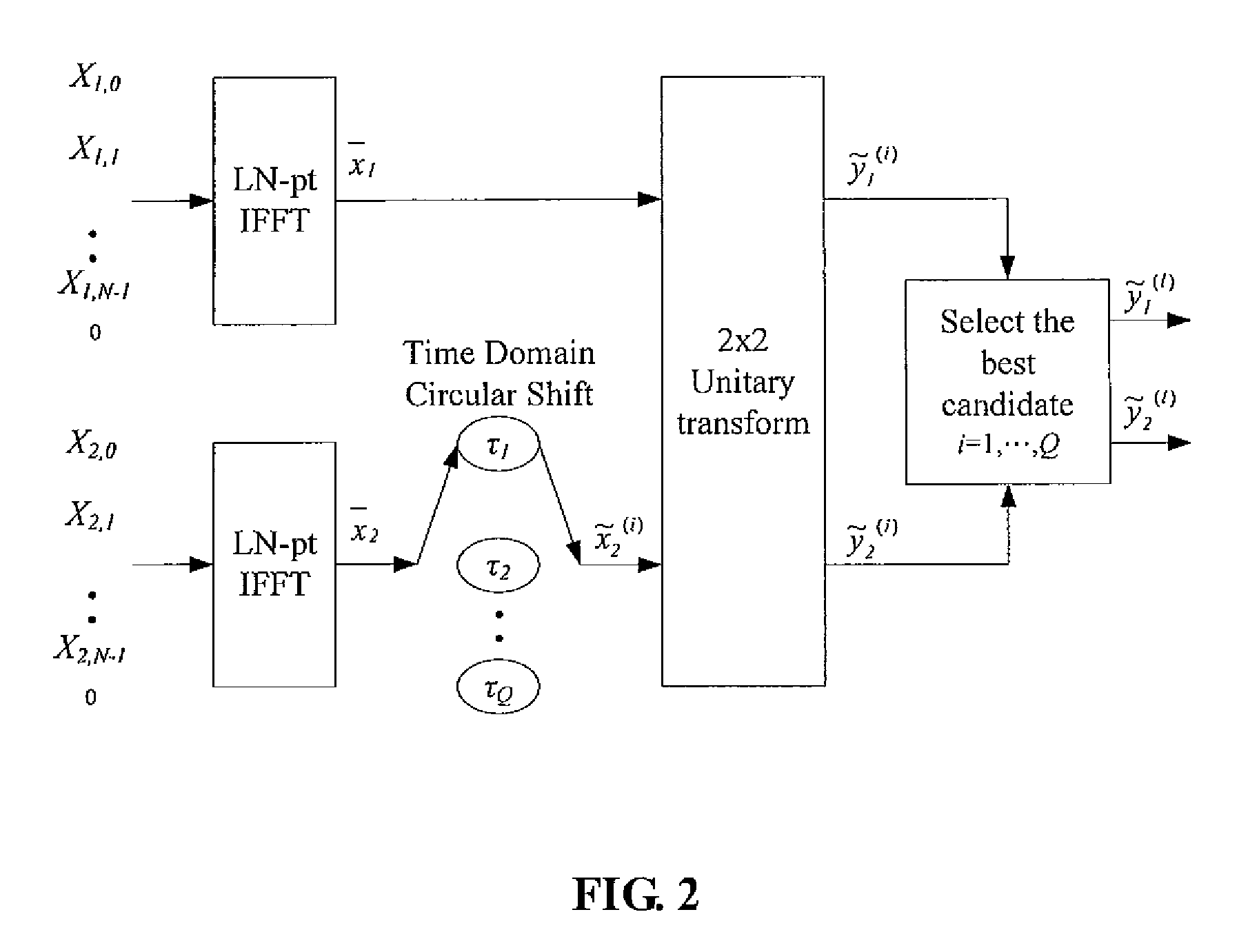
[0019]FIG. 2 is a schematic diagram showing the present invention, which performs 2×2 unitary transforms for a MCM system having N (N≧2) sub-carriers.
[0020]First in step 1, in order to achieve more accurate estimation of the PAPR, the present embodiment supplements (L−1)N zeros (L≧1) to the baseband signal blocks X1=(X1,0, X1,1, . . . , X1,N−1) and X2=(X2,0, X2,1, . . . , X2,N−1) generated from the MCM system with N sub-carriers, respectively, so that X1 and X2 become (X1,0, X1,1, . . . , X1,N−1, 0, . . . , 0) and (X2,0, X2,1, . . . , X2,N−1, 0, . . . , 0).
[0021]The baseband signal blocks X1 and X2 then undergo LN-point IFFT (denoted as “LN-pt IFFT” in the drawing), respectively, to obtain L-time oversampled time-domain signal blocks x1=(x1,0, x1,1, . . . , x1,LN−1) and x2=(x2,0, x2,1, . . . , x2,LN−1).
[0022]Subsequently, in step 2, x2 undergoes Q (Q≧1) different Time Domain Circular Shift with parameters τ1, τ2, . . . , τQ (all greater than zero) to obtain {tilde over (x)}2(i)=TS( ...
second embodiment
[0032]FIG. 3 is a schematic diagram showing the present invention, which performs circular shift in the frequency domain in contrast to the circular shift in the time domain performed by the previous embodiment.
[0033]Step 1 is identical to the previous embodiment and (L−1)N zeros (L≧1) are supplemented to the baseband signal blocks X1=(X1,0, X1,1, . . . , X1,N−1) and X2=(X2,0, X2,1, . . . , X2,N−1) generated from the MCM system with N sub-carriers, respectively, so that X1 and X2 become (X1,0, X1,1, . . . , X1,N−1, 0, . . . , 0) and (X2,0, X2,1, . . . , X2,N−1, 0, . . . , 0). The baseband signal blocks X1 and X2 then undergo LN-point IFFT (denoted as “LN-pt IFFT” in the drawing), respectively, to obtain L-time oversampled time-domain signal blocks x1=(x1,0, x1,1, . . . , x1,LN−1) and x2=(x2,0, x2,1, . . . , x2,LN−1).
[0034]Then, in step 2, x2 is processed by the following function for Q times sequentially:
PUM
Abstract
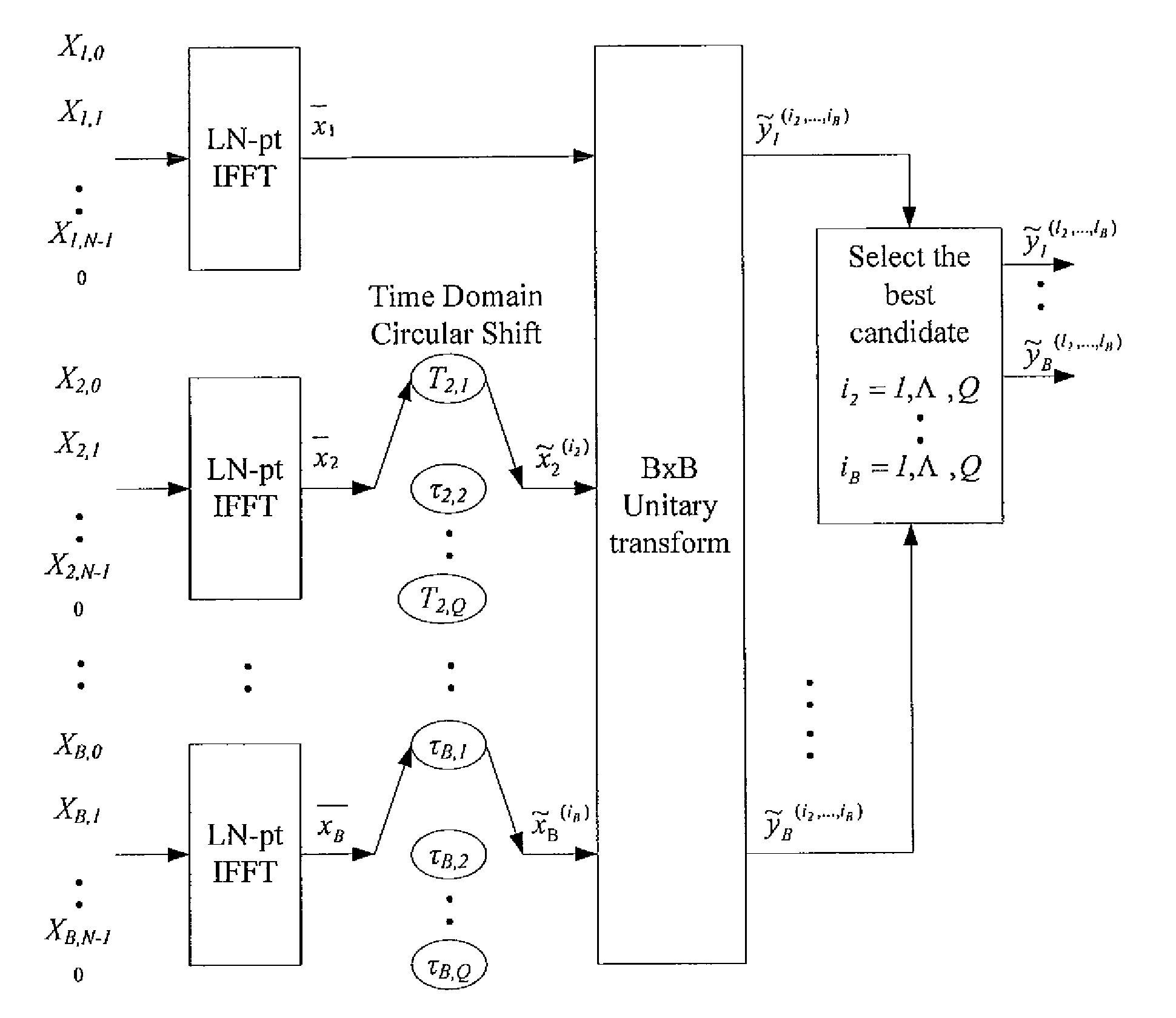
The method contains the following steps. First, in a MCM system with N sub-carriers, the basebandsignal blocks Xj, j=1, 2, . . . ,B are supplemented with zeros and processed with LN-point IFFT, respectively, to obtain L-time oversampled time-domain signal blocks xj, j=1,2, . . . ,B. Then, xj undergoes Q Time Domain Circular Shifts or Frequency Domain Circular Shifts to obtain Q signal blocks {tilde over (x)}j(i<sub2>j< / sub2>), ij=1, Λ, Q. Subsequently, a B×B unitary transform is performed against ( x1, {tilde over (x)}2(i<sub2>2< / sub2>), . . . , {tilde over (x)}B(i<sub2>B< / sub2>)). After the unitary transform, for each (i2, . . . , iB) a combination having B time-domain signal blocks is obtained as follows: ({tilde over (y)}1(i<sub2>2< / sub2>, . . . , i<sub2>B< / sub2>), {tilde over (y)}2(i<sub2>2< / sub2>, . . . , i<sub2>B< / sub2>), . . . , {tilde over (y)}B(i<sub2>2< / sub2>, . . . ,i<sub2>B< / sub2>))=( x1, {tilde over (x)}2(i<sub2>2< / sub2>), . . . , {tilde over (x)}B(i<sub2>B< / sub2>)) cU where U is the B×B unitary matrix, and c is an arbitrary constant (c≠0). Finally, the total QB−1 combinations are compared against each other to select a best candidate for transmission that could produce the lowest peak value, or the smallest PAPR, or the lowest clipping noise power.
Application Information
Patent Timeline
Application Date:The date an application was filed.
Publication Date:The date a patent or application was officially published.
First Publication Date:The earliest publication date of a patent with the same application number.
Issue Date:Publication date of the patent grant document.
PCT Entry Date:The Entry date of PCT National Phase.
Estimated Expiry Date:The statutory expiry date of a patent right according to the Patent Law, and it is the longest term of protection that the patent right can achieve without the termination of the patent right due to other reasons(Term extension factor has been taken into account ).
Invalid Date:Actual expiry date is based on effective date or publication date of legal transaction data of invalid patent.

