

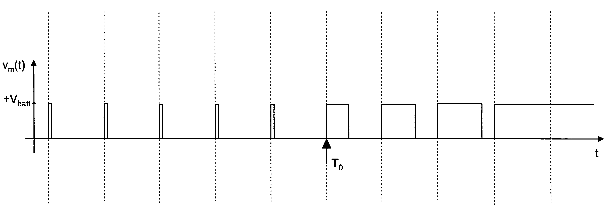
Method for controlling an electric motor by using the PWM Technique
a technology of electric motors and dielectrics, applied in the direction of electric controllers, dc motor rotation control, instruments, etc., can solve the problems of failure of capacitors, failure of capacitor dielectrics, and relatively frequent failure of vehicles, so as to achieve easy and cost-effective implementation
- Summary
- Abstract
- Description
- Claims
- Application Information
AI Technical Summary
Benefits of technology
Problems solved by technology
Method used
Image

Examples
Embodiment Construction
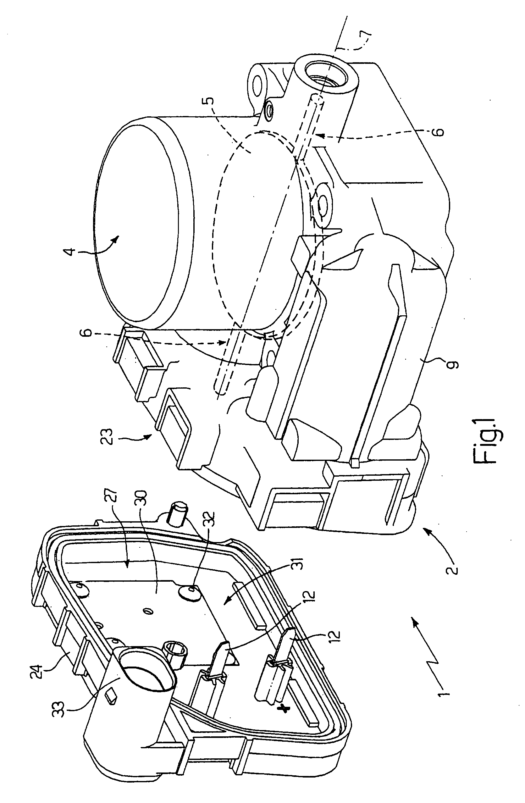
[0015]In FIG. 1, numeral 1 indicates as a whole an electronically controlled butterfly valve for an internal combustion engine (not shown). The butterfly valve 1 includes a valve body 2 accommodating an actuator device provided with a direct current electric motor 3 (shown in FIG. 2), a circular section tubular feeding pipe 4 through which the air taken in by the internal combustion engine flows, and a butterfly plate 5 (diagrammatically shown with a broken line), which is circular shaped, engages the feeding pipe 4 and rotates between an opening position and a closing position of the feeding pipe 4 by effect of the action of an actuator device. The butterfly plate 5 is keyed onto a rotating shaft 6 featuring a longitudinal rotation axis 7 to rotate under the control of the actuator device between the opening position and the closing position by the effect of the action of the actuator device.
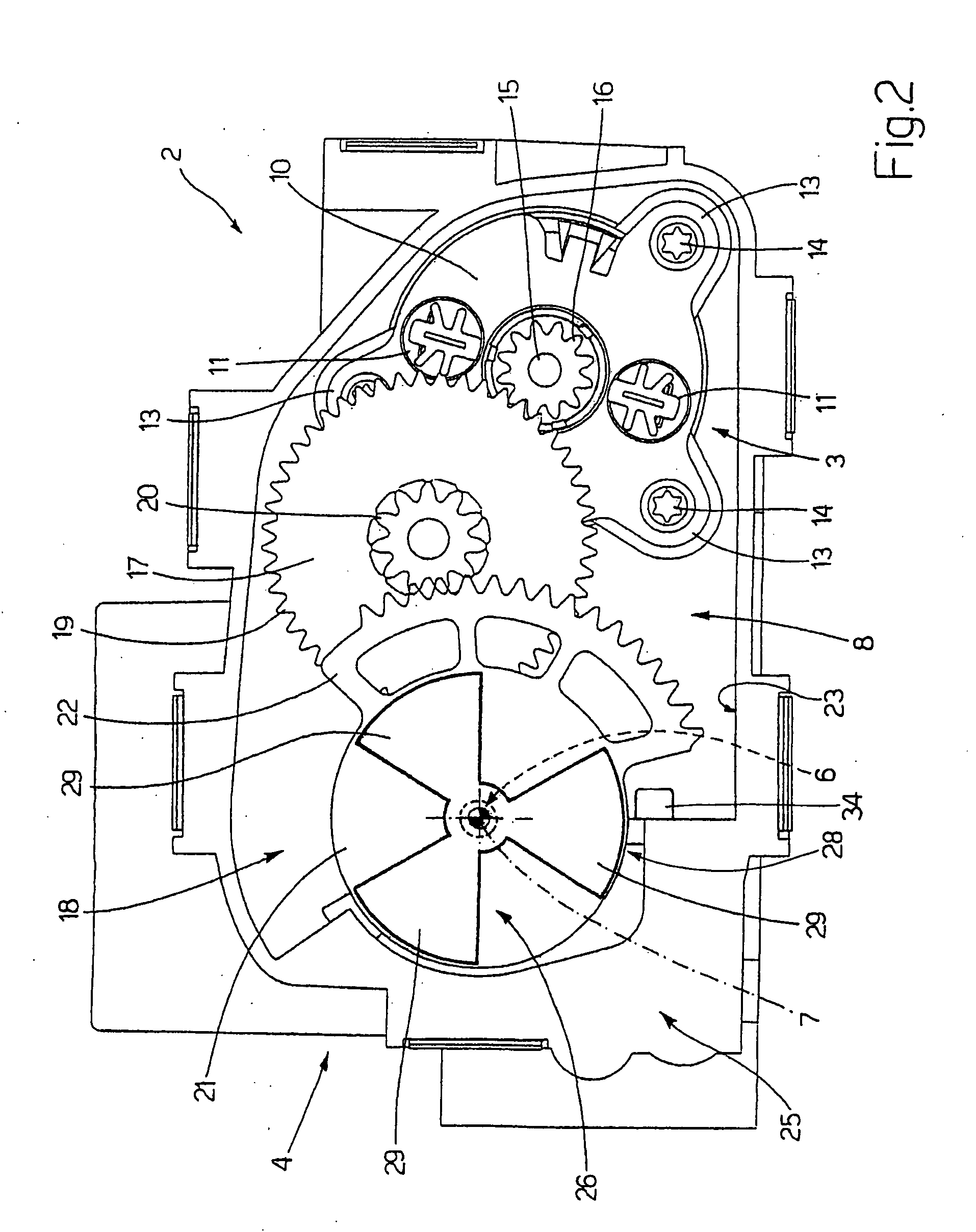
As shown in FIG. 2, the actuator device includes the electric motor 3 which is coupled to t...
PUM
 Abstract
Description
Claims
Application Information