Abradable coating system

a technology of abrasion and coating, applied in the direction of machines/engines, stators, liquid fuel engines, etc., can solve the problems of increasing the inefficiency increasing the incidence of rubbing between the blade tips of the turbine blade and the outer ring seal, and the typical problem of the turbine engine, so as to reduce or eliminate the spallation of thermal barrier coating (tbc) and relieve thermally-induced strains

Inactive Publication Date: 2009-06-11
SIEMENS ENERGY INC
View PDF24 Cites 44 Cited by
  • Summary
  • Abstract
  • Description
  • Claims
  • Application Information

AI Technical Summary

Benefits of technology

[0014]Another advantage of the invention is that the abradable coating reduces or eliminates thermal barrier coating (TBC) spallation due to thermal cycling since the columnar structure naturally relieves thermally-induced strains caused by the contraction and expansion of the underlying metal substrate.
[0015]Yet another advantage of the invention is that the abradable coating may include an alarm system and thermocouples for monitoring the performance and condition of the abradable coating system and the turbine engine.
[0016]These and other embodiments are described in more detail below.

Problems solved by technology

The gaps between the turbine blade tips and the ring seal segments are designed to be as small as possible between the blade tips and the surrounding segment because the larger that gap, the more inefficient the turbine engine.
However, as the gap is reduced, the incidences of rubbing between the turbine blade tips and the outer ring seal increases.
While the gap between the tips of the turbine blade and the ring seal segments may be designed to enable smooth startup from a cold engine, problems are typically encountered during a warm restart.
A problem that is widespread with abradable coatings is that the coatings generally sinter after exposure to turbine engine operating temperatures of about 2,500 degrees Fahrenheit after about 50 to 100 hours.
Sintering of the abradable coating significantly reduces the abradable coatings ability to shear when contacted by tips of turbine blades.

Method used


Image

  • Abradable coating system
  • Abradable coating system
  • Abradable coating system

Examples


Embodiment Construction

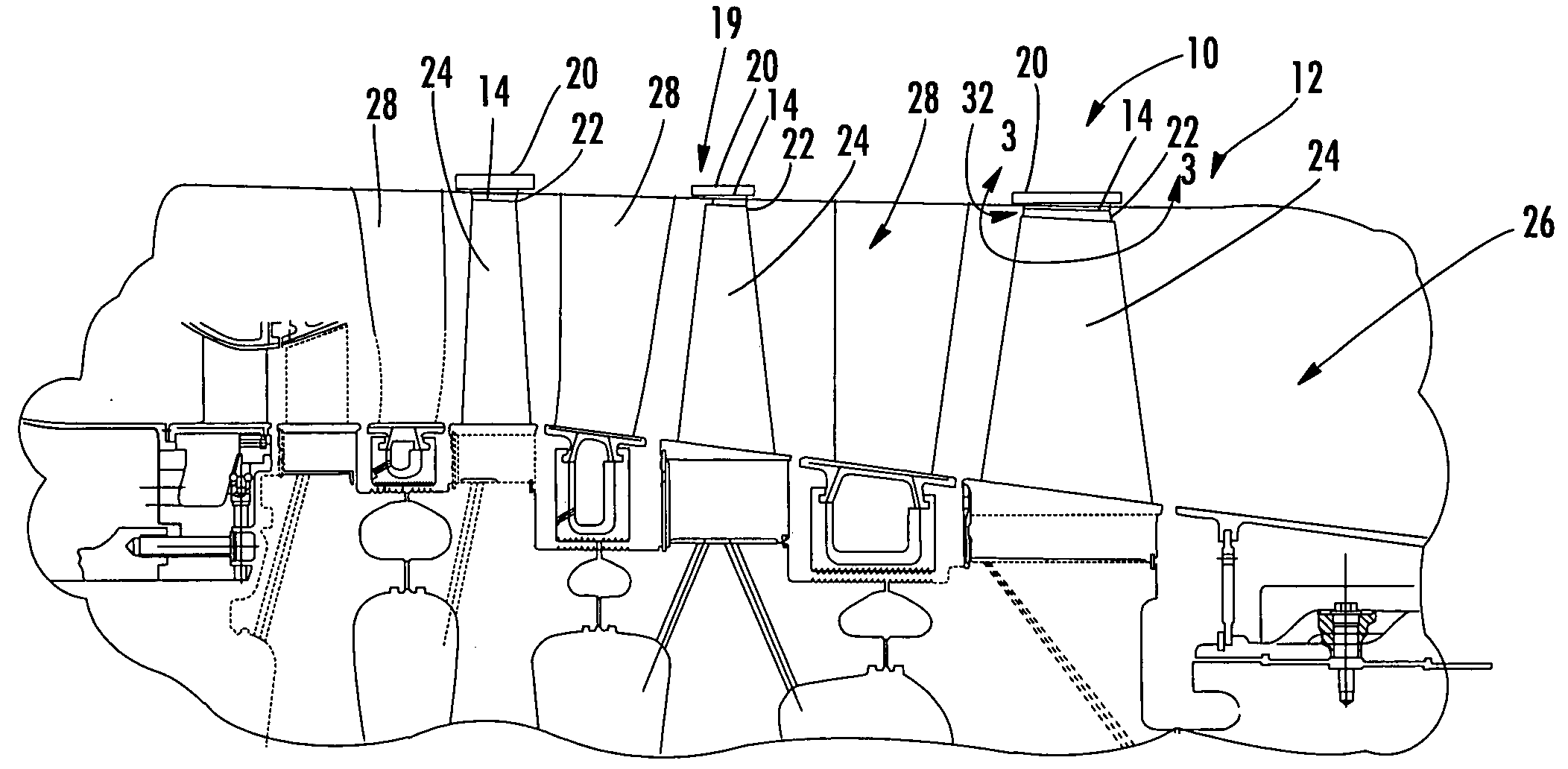
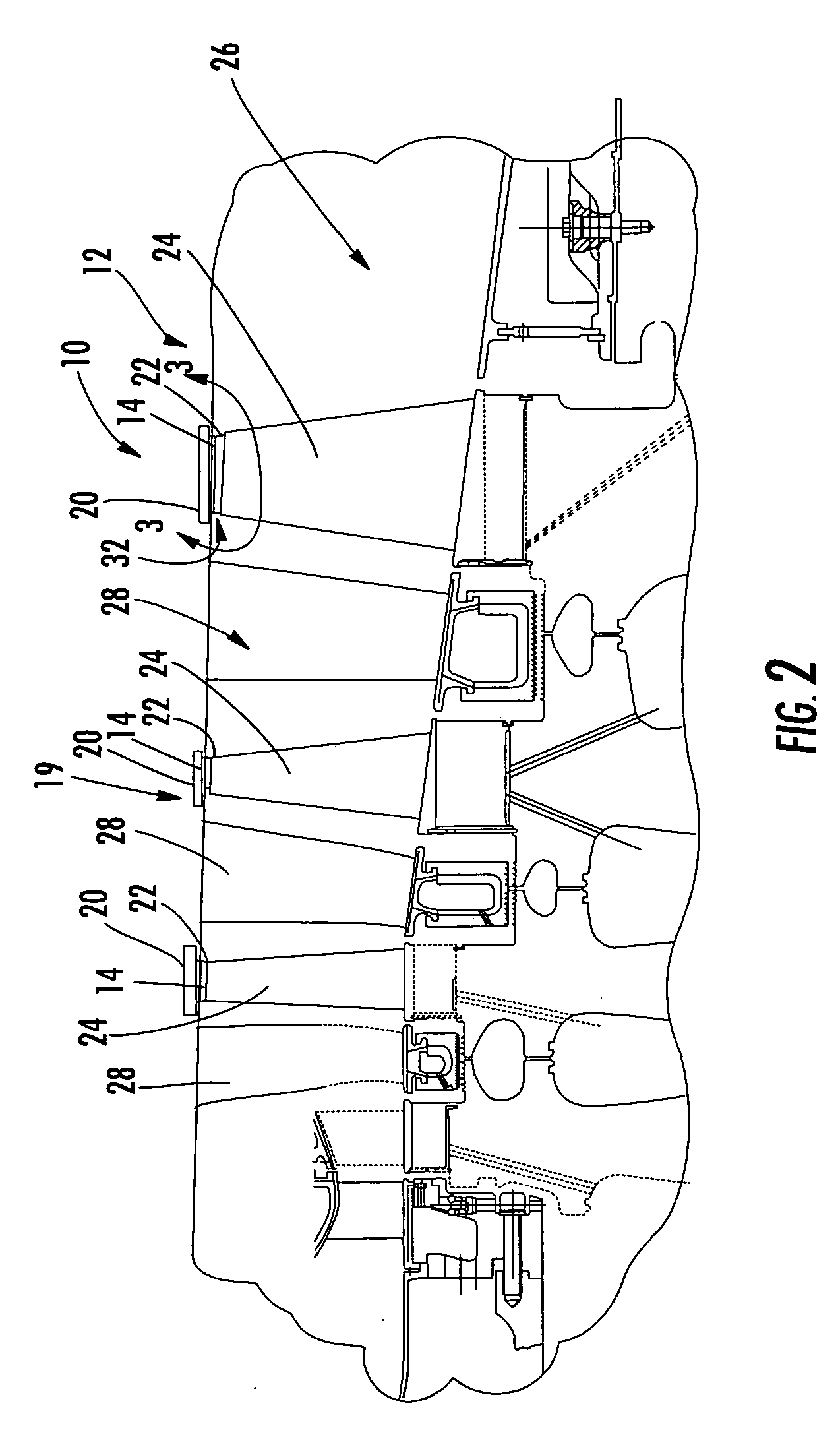
[0032]As shown in FIG. 2-14, this invention is directed to an abradable coating system 10 for use in turbine engines 12. In particular, the abradable coating system 10 may include an abradable coating 14 formed from a plurality of columns 16 that limit sintering of the coating 14 to outermost portions of the coating 14, thereby enabling the columns 16 forming the abradable coating 14 to shear off near the base 18 of the columns 16. The abradable coating 14 may be applied to an outer surface 17 of a turbine component 19, such as, but not limited to, one or more turbine ring seal segments 20. The turbine ring seal segments 20 may be positioned radially outward from tips 22 of turbine blades 24 to create a seal between the turbine blades 24 and the surrounding ring seal segments 20. The abradable coating system 10 may be formed an abradable material and may have a columnar configuration that prevents bases 18 of the columns 16 from sintering, thereby enabling the columns 16 to break at...


PUM

PropertyMeasurementUnit
thicknessaaaaaaaaaa
thicknessaaaaaaaaaa
areaaaaaaaaaaa

Abstract

This invention relates to an abradable coating system for use in axial turbine engines. When coated onto a turbine ring seal segment the coating system may allow formation of an individualized seal between turbine blade disks and the surrounding ring seal without causing excessive wear to the blade tips. The abradable coating system includes columns of an abradable material. Thus, interference between the blades and the abradable coating system causes the individual columns to break off at the base. This abrasion mechanism may reduce blade wear and spalling of the coating system when compared to conventional coatings.

Description

FIELD OF THE INVENTION[0001]This invention is directed generally to abradable coating systems, and more particularly to abradable coating systems useful for creating individualized seals between turbine blades and corresponding ring segment shrouds.BACKGROUND[0002]Axial gas turbines typically contain rows of turbine blades, referred to as stages, coupled to disks that rotate on a rotor assembly. The turbine blades extend radially and terminate in turbine blade tips. Ring seal segments are positioned radially outward from the turbine blade tips, but in close proximity to the tips of the turbine blades to limit gases from passing through the gap created between the turbine blade tips and the inner surfaces of the ring seal segments. The gaps between the turbine blade tips and the ring seal segments are designed to be as small as possible between the blade tips and the surrounding segment because the larger that gap, the more inefficient the turbine engine.[0003]The size of the gap bet...

Claims


Application Information

Patent Timeline
Patent Type & Authority Applications(United States)
IPC IPC(8): F01D11/12F01D25/00F01D21/14
CPCC23C26/00F01D11/125F01D11/127Y10T428/24157F05D2300/21F05D2300/611F05C2225/08
Inventor ALLEN, DAVID B.
Owner SIEMENS ENERGY INC
Why Eureka
Try Eureka