Glass and carbon fiber composites and uses thereof

a technology of carbon fiber and composites, which is applied in the field of glass fiber (gf) and carbon fiber (cf) composites, can solve the problems of high cost of use alone, low load retention of composites, and high brittleness, and achieves high energy absorption ability, high stiffness, and high resistance to ruptur

Inactive Publication Date: 2020-05-07
DUPONT POLYMERS INC
View PDF2 Cites 3 Cited by
  • Summary
  • Abstract
  • Description
  • Claims
  • Application Information

AI Technical Summary

Benefits of technology

[0007]It is an aim of this invention to provide a carbon fiber based composite material that has a high stiffness yet has a high energy absorption ability and strain to rupture.

Problems solved by technology

In particular, carbon composites have excellent weight specific properties due to the high fiber modulus but in many applications are considered to be too expensive when used alone.
A further drawback of long carbon fiber (CF) or continuous CF thermosets in certain applications is that they may be too brittle.
Thermoplastic CF composites are believed to be tougher, as are thermoplastic CF / glass fiber (GF) hybrid multilayer laminates, yet, with the very high fiber loadings needed for high modulus and strength, the composites still have low load retention after initial failure in flexural testing.
Moreover, the impregnation of fibrous material made of carbon fibers with thermoplastic polymer resins can be particularly challenging.
Therefore, composite manufacturers are facing the dilemma that end applications need increased stiffness as compared to glass fiber composite but at lower costs than full carbon fiber, while significant energy absorption properties are needed where it is advantageous and desired to enable load triggering and tailored rip-through in the part where high levels of force can be maintained for greater displacements.

Method used


Image

  • Glass and carbon fiber composites and uses thereof
  • Glass and carbon fiber composites and uses thereof
  • Glass and carbon fiber composites and uses thereof

Examples


example 1

of Composite Structures of the Invention and Comparative Examples

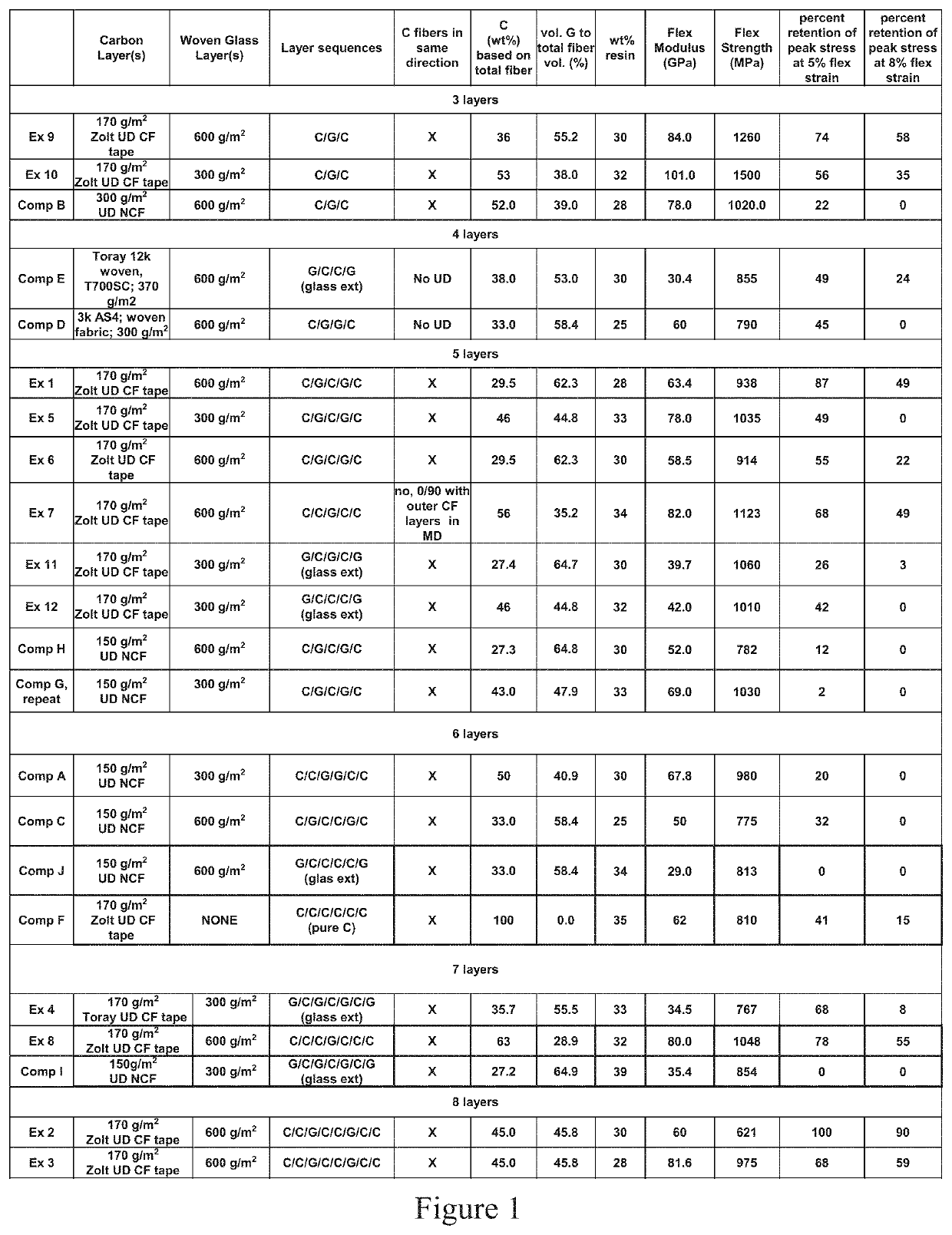
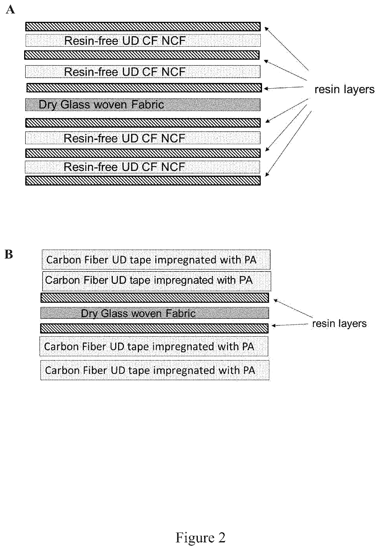
[0109]Different composite structures of the invention were prepared according to sequence as described in FIG. 2A and compared to standard composites prepared according to a sequence as described in FIG. 2A.

Composite of the Invention Ex. 1-12

[0110]Pre-impregnated UD carbon fiber tapes were used without the addition of any further PA66 film layer adjacent to the pre-impregnated UD carbon fiber tapes. Film layers of PA66 were added adjacent to the layers of resin-free glass fabric so this fabric could be impregnated during thermal pressing or lamination as described herein.

example 2

aracterization of the Inner Structure of Composites of the Invention as Compared to Comparative Examples

[0134]Structures of the composites of the invention were analyzed by microscopy of cross sections of a laminate of Example 1 as compared to a laminate of a composite from comparative example (Comp. Ex. A). FIG. 4 presents photographs of cross-sections as observed by microscopy described above.

[0135]As can be seen on FIG. 4A, more resin is observed within CF regions and less within the GF layer (5B) in the laminate of the composite of the invention. The cross section of a laminate of the invention can be schematized as represented on FIG. 5B. In general, for laminates of the invention, within the CF bundles between 43 and 49 vol % CF are observed as compared to comparative examples where between 54 and 66 vol % CF are observed in the CF regions (FIG. 5A). In FIGS. 4 and 5, the total resin weight percent within the laminates are about 30 wt %, and the total weight percent carbon rel...


PUM

PropertyMeasurementUnit
weight fractionaaaaaaaaaa
volume fractionaaaaaaaaaa

Abstract

The present invention relates to novel glass-carbon composites presenting very high directional properties in the UD carbon layer direction greater with improved failure mode as compared to full carbon fiber and standard composite fibers. The invention further relates to a process of preparation of such glass-carbon composites and to articles made from such glass-carbon composites.

Description

FIELD OF THE INVENTION[0001]This invention relates to glass fiber (GF) and carbon fiber (CF) composites for use in composite structures, for instance for use in automotive, industrial, consumer, or aerospace applications.BACKGROUND OF THE INVENTION[0002]With the aim of replacing metal parts for weight saving and cost reduction while having comparable or superior mechanical performance, structures based on composite materials comprising a polymer matrix containing a fibrous material have been developed.[0003]In highly demanding applications, such as for example structural parts in automotive and aerospace applications, composite materials are desired due to a unique combination of light weight, high strength and temperature resistance.[0004]High performance composite structures can be obtained using thermosetting resins or thermoplastic resins as the polymer matrix. Thermoplastic-based composite structures present several advantages over thermoset-based composite structures including...

Claims


Application Information

Patent Timeline
Patent Type & Authority Applications(United States)
IPC IPC(8): B29C70/08B29C70/34B32B5/02B32B5/12B32B5/26
CPCB29L2031/30B32B5/12B32B5/26B32B2262/106B32B2262/101B29K2307/04B29C70/34B32B2605/00D03D15/0011B32B5/024B29K2309/08B32B2250/05B29C70/083B29C70/467B32B17/04B32B2250/40B32B2260/023B32B2260/046B32B2307/306B32B2307/546B32B2307/558B32B2307/56B32B2605/08B32B2605/18C08J5/042C08J5/043C08J2377/06D03D15/267
Inventor SAUER, BRYAN BENEDICTWAKEMAN, MARTYN DOUGLAS
Owner DUPONT POLYMERS INC
Why Eureka
Try Eureka