
Mitral valve treatment techniques

a technology of mitral valve and treatment technique, which is applied in the field of surgical methods and equipment, can solve the problems of increasing the risk of progressive heart failure, and achieve the effect of enhancing fibrosis and changing the shape of the hear

Active Publication Date: 2009-06-11
VALTECH CARDIO LTD
View PDF52 Cites 158 Cited by
  • Summary
  • Abstract
  • Description
  • Claims
  • Application Information

AI Technical Summary

Benefits of technology

[0107]For some applications, the applicator is configured to enhance fibrosis between at least a portion of the applicator and the wall of the chamber.
[0113]In an embodiment, the applicator is configured such that after placement of the applicator, and before the at least two regions apply the force, there is a gap between the applicator and the wall of the chamber. For some applications, the applicator is configured such that the force applied by the at least two regions reduces a distance between the applicator and the wall of the chamber in a vicinity of the gap. For some applications, the applicator is configured such that the force applied by the at least two regions immediately reduces the distance. Alternatively, the applicator is configured such that the force applied by the at least two regions reduces the distance within one month of application of the force.
[0117]enhance fibrosis between at least a portion of the force applicator and the heart wall, so as to help maintain the changed shape of the heart.
[0121]There is also provided, in accordance with an embodiment of the present invention, a method for treating mitral valve regurgitation, including placing, around at least a portion of a mitral valve of a heart, a force applicator configured to apply force to a wall of a chamber of the heart, so as to change a shape of the heart around the mitral valve, and to enhance fibrosis between at least a portion of the force applicator and the heart wall, so as to help maintain the changed shape of the heart.

Problems solved by technology

Regurgitation caused by a defective mitral valve reduces cardiac output, increasing the risk of progressive heart failure.

Method used


Image

  • Mitral valve treatment techniques
  • Mitral valve treatment techniques
  • Mitral valve treatment techniques

Examples


Embodiment Construction

[0148]FIG. 1 is a schematic illustration of a mitral valve treatment device 20, in accordance with an embodiment of the present invention. Device 20 typically comprises a flexible band 30, a distal coupling element 32 (e.g., a hook), and a proximal coupling element 34 (e.g., a hook). For some applications, band 30 is generally elliptical in cross-section (e.g., circular), while for other applications the band is flat, e.g., ribbon-shaped.

[0149]Band 30 typically comprises a biocompatible material, such as a polymer or metal. For some applications, band 30 is coated with a drug and / or a radiopaque coating.

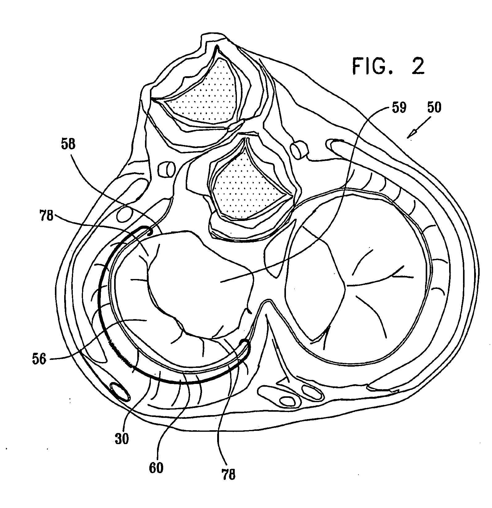
[0150]Reference is made to FIG. 2, which is a schematic illustration of band 30 placed in a heart 50, which is viewed from above the heart with the atria removed, in accordance with an embodiment of the present invention. Band 30 is adapted to be placed around between 90 and 270 degrees of a mitral valve 58 of a heart 50, including around at least a portion of a posterior cusp 56 of ...


PUM


Abstract

Apparatus (20) is provided for treating mitral valve regurgitation, including a band (30) having distal and proximal ends, the band (30) adapted to be placed: around between 90 and 270 degrees of a mitral valve (58), including around at least a portion of a posterior cusp (56) of the valve (58), in a space defined by (a) a ventricular wall (70), (b) a ventricular surface of the posterior cusp (56) in a vicinity of an annulus (60) of the mitral valve (58), and (c) a plurality of third-order chordae tendineae (74). The apparatus (20) further includes distal and proximal coupling elements (32, 34), coupled to the band (30) at the distal and proximal ends thereof, respectively, and adapted to be coupled to a first chorda tendinea and a second chorda tendinea, respectively, each of the first and second chordae tendineae selected from the group consisting of: one of the plurality of third-order chordae tendineae (74), and a first-order chorda tendinea that inserts on a commissural cusp (78) of the mitral valve (58). Additional embodiments are also described.

Description

CROSS-REFERENCES TO RELATED APPLICATIONS[0001]The present application claims the benefit of: (a) U.S. Provisional Patent Application 60 / 662,616 to Gross et al., filed Mar. 17, 2005, and (b) U.S. Provisional Patent Application 60 / 700,542 to Gross et al., filed Jul. 18, 2005. Both of these applications are assigned to the assignee of the present application and are incorporated herein by reference.FIELD OF THE INVENTION[0002]The present invention relates generally to surgical methods and apparatus, and specifically to methods and apparatus for mitral valve treatment.BACKGROUND OF THE INVENTION[0003]Mitral valve regurgitation is a disorder in which the mitral valve does not close properly. During systole, a healthy mitral valve prevents oxygenated blood from flowing back (regurgitating) from the left ventricle to the left atrium. Regurgitation caused by a defective mitral valve reduces cardiac output, increasing the risk of progressive heart failure. Treatments for mitral valve regurgi...

Claims


Application Information

Patent Timeline
Patent Type & Authority Applications(United States)
IPC IPC(8): A61B17/08A61F5/00A61B17/10
CPCA61B2017/00243A61F2/2445A61F2/2466A61F2250/0003A61F2250/0004A61F2/2457A61F2220/0008A61F2220/0025A61F2250/0007A61F2250/0096A61F2/2442A61F2/2409A61F2/2448A61F2/2418
Inventor GROSS, AMIRGROSS
Owner VALTECH CARDIO LTD
Learn More