Modulator timing for quantum key distribution

a modulator and key technology, applied in the field of quantum cryptography, to achieve the effect of reducing modulation errors

Inactive Publication Date: 2009-06-11
MAGIQ TECH INC
View PDF12 Cites 11 Cited by
  • Summary
  • Abstract
  • Description
  • Claims
  • Application Information

AI Technical Summary

Benefits of technology

[0010]In an example embodiment where the QKD system is a two-way system, one of the pulses is modulated both as it enters and as it leaves Alice. This allows for Alice's modulator to modulate the pulse for orthogonal polarizations. Since phase modulators tend to be polarization sensitive, this approach serves to reduce modulation error that results from polarization variations in the pulses.

Problems solved by technology

As a consequence, an eavesdropper (“Eve”) that attempts to intercept or otherwise measure the quantum signal will introduce errors into the transmitted signals, thus revealing her presence.

Method used


Image

  • Modulator timing for quantum key distribution
  • Modulator timing for quantum key distribution
  • Modulator timing for quantum key distribution

Examples


Embodiment Construction

[0014]The present invention relates to and has industrial utility with respect to quantum cryptography, and is directed to systems and methods for performing modulation of quantum signals in a QKD system. The invention is discussed below in connection with a two-way QKD system, though the invention is applicable to both one-way and two-way systems. In the discussion below, a “quantum signal” or “quantum pulse” has an average number of photons μ≦1, and a “non-quantum signal” or “non-quantum pulse” has an average number of photons μ>1.

Ideal Operation of a Two-Way QKD System

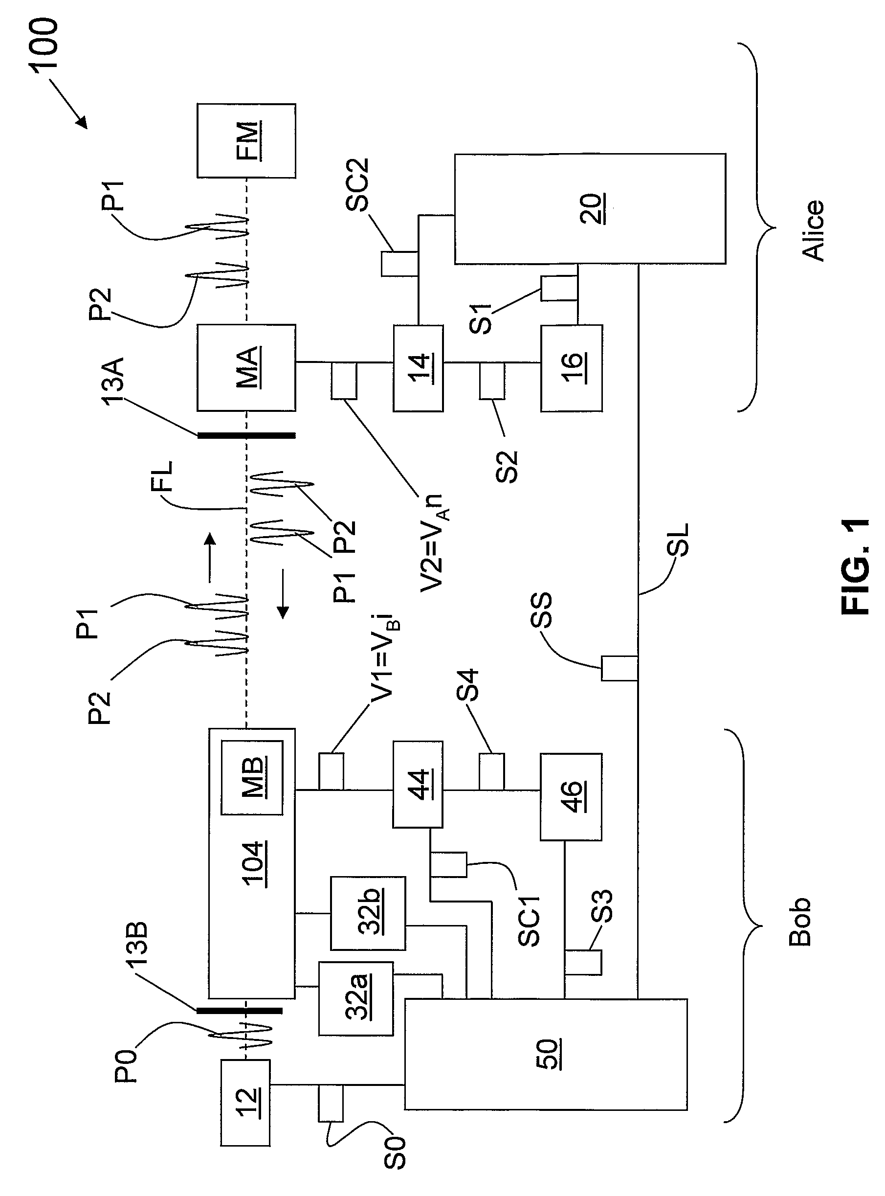
[0015]For the sake of illustration, the present invention is described in connection with a two-way QKD system. FIG. 1 is a schematic diagram of a two-way QKD system 100 that includes two QKD stations, Alice and Bob. Bob includes laser 12 that emits light pulses P0. Laser 12 is coupled to a time-multiplexing / demultiplexing (M / D) optical system 104. M / D optical system 104 receives input pulses P0 from laser 12 and sp...


PUM


Abstract

Methods for establishing modulator timing for a QKD system (100) having QKD stations (Alice, Bob) with respective modulators (MA, MB) are disclosed. The timing method includes exchanging non-quantum signals (P1, P2) between the two QKD stations and performing respective coarse timing adjustments by scanning the modulator timing domain with relatively coarse timing intervals (ΔT1C, ΔT2C,) and wide (coarse) modulator voltage signals (W1C, W2C). Coarse timings (T1C, T2C) are established by observing a change in detector counts between single-photon detectors (32a, 32b) when modulation occurs in exchanged non-quantum signals. The method also includes performing a fine timing adjustment by scanning the modulator timing domain with respective fine timing intervals (ΔT1R, ΔT2R) and respective relatively narrow modulator voltage signals (W1R, W2R), and again observing a change in detector counts for exchanged non-quantum signals. This operation is repeated until desired final modulator timings (T1F, T2F) and desired final activation signal widths (W1F, W2F) are obtained for the two modulators.

Description

CLAIM OF PRIORITY[0001]This patent application claims priority from U.S. patent application Ser. No. 60 / 549,356, filed on Mar. 2, 2004.TECHNICAL FIELD OF THE INVENTION[0002]The present invention relates to quantum cryptography, an in particular relates to a method for establishing the timing of the operation of modulators in a quantum key distribution (QKD) system.BACKGROUND ART[0003]Quantum key distribution involves establishing a key between a sender (“Alice”) and a receiver (“Bob”) by using weak (e.g., 0.1 photon on average) optical signals transmitted over a “quantum channel.” The security of the key distribution is based on the quantum mechanical principle that any measurement of a quantum system in unknown state will modify its state. As a consequence, an eavesdropper (“Eve”) that attempts to intercept or otherwise measure the quantum signal will introduce errors into the transmitted signals, thus revealing her presence.[0004]The general principles of quantum cryptography were...

Claims


Application Information

Patent Timeline
Patent Type & Authority Applications(United States)
IPC IPC(8): G06F15/16H04K1/00H04L9/00H04L9/08
CPCH04L9/0858H04B10/70
Inventor VIG, HARRY
Owner MAGIQ TECH INC
Why Eureka
Try Eureka