

Methods and Systems to Enhance Efficiency of Power-Transmission Systems Containing Higher Viscosity Lubricants
- Summary
- Abstract
- Description
- Claims
- Application Information
AI Technical Summary
Benefits of technology
Problems solved by technology
Method used
Image

Examples
Embodiment Construction
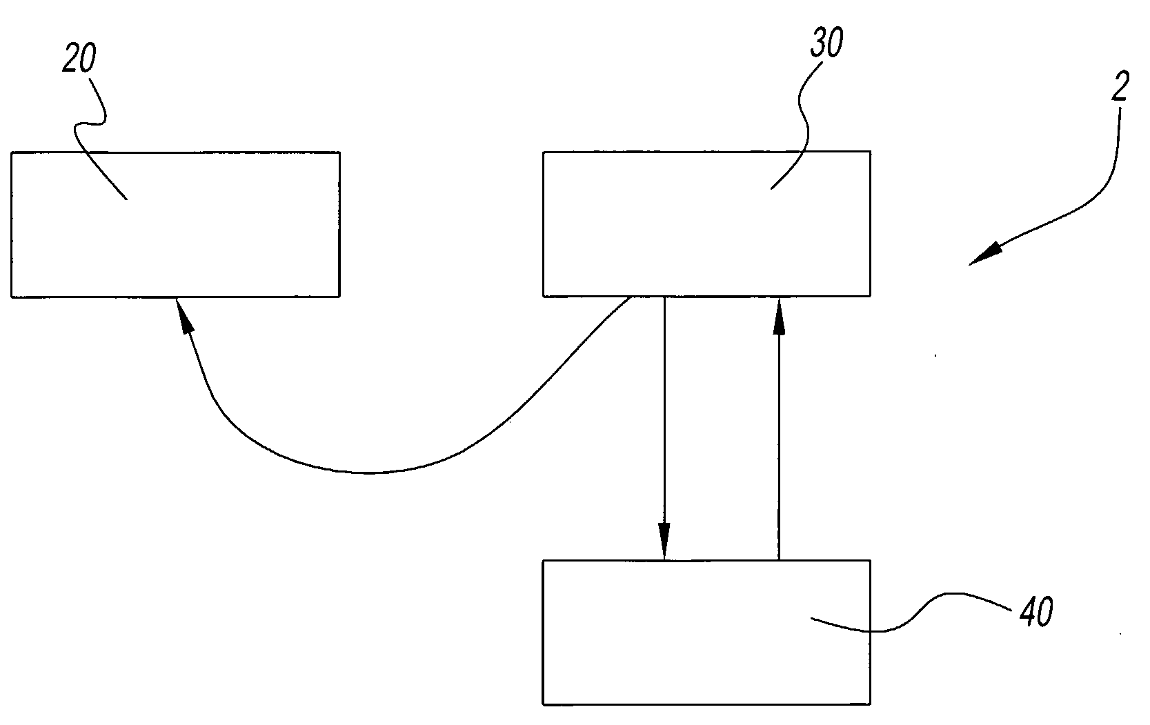
[0018]Referring to the drawings and in particular to FIG. 1, an exemplary embodiment of a method of producing a power transmission system is generally illustrated as reference numeral 2.
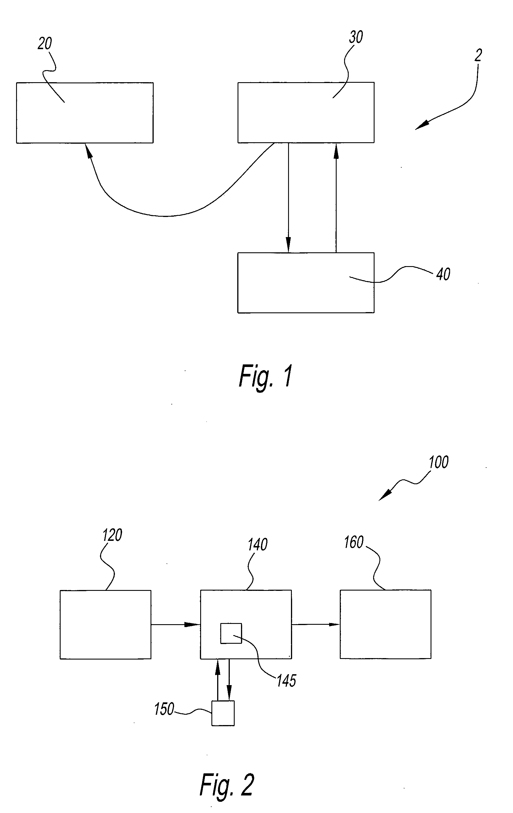
[0019]Method 2 includes the first step 20 of obtaining power transmission components 145. These components 145 may be, for example, intermeshing gears, bearings, springs, and / or splines, etc. At least some of the components 145 may be processed using a chemically accelerated vibratory finishing process to refine (reduce the roughness of) the contact surfaces of the components. According to this chemically accelerated vibratory finishing process, components composed of various metals and / or alloys may be placed into a processing hopper in the presence of processing chemicals and vibratory media. The chemicals are preferably selected such that they react with the metallic components that are being processed to form a soft metal-oxide that is removed, through interaction with the vibratory media, to exp...
PUM
| Property | Measurement | Unit |
|---|---|---|
| Temperature | aaaaa | aaaaa |
| Temperature | aaaaa | aaaaa |
| Kinematic viscosity | aaaaa | aaaaa |
Abstract
Description
Claims
Application Information