Piston for Internal Combustion Engine and Internal Combustion Engine with the Same

a technology for internal combustion engines and pistons, which is applied in the direction of engine cooling apparatus, machines/engines, liquid cooling, etc., can solve the problems of increasing the number of components used in the piston, increasing the temperature in such areas, and heat from flowing, so as to facilitate the production of the piston, efficiently deliver the oil to the second cavity, and efficiently cool the area surrounding the second cavity

Inactive Publication Date: 2009-06-18
TOYOTA JIDOSHA KK
View PDF7 Cites 13 Cited by
  • Summary
  • Abstract
  • Description
  • Claims
  • Application Information

AI Technical Summary

Benefits of technology

[0013]According to the first aspect, the through hole may be angled in the axial direction of the piston. This helps oil flow toward the second cavity, thereby delivering the oil to the second cavity efficiently, and thus cooling the area surrounding the second cavity efficiently.
[0014]In addition, according to the first aspect, the land may be provided with an oil return hole to communicate with the second cavity, and the through hole and the oil return hole may be located along a common straight line. This enables the through hole and the oil return hole to be machined simultaneously with a single boring process. Such simplified boring process for forming the through hole and the oil return hole facilitates production of the piston, and therefore improves the productivity thereof. An oil ring is fitted into the land. Oil scraped off by the oil ring returns to the second cavity through the oil return hole, cooling the area surrounding the second cavity. This further prevents a decrease in cooling performance in the area surrounding the second cavity. Consequently, the entire piston is effectively cooled, thereby improving the cooling performance in the piston.
[0015]A second aspect of the invention is directed to an internal combustion engine. The internal combustion engine includes: the piston for an internal combustion engine according to the first aspect; and an oil jet for spraying oil toward the undersurface of the piston head of the piston for an internal combustion engine. The internal combustion engine thus constructed allows oil, which is sprayed from an oil jet and splashed onto the undersurface of the piston head, to diffuse in the first cavity on the undersurface of the piston head. At the same time, part of the diffusing oil flows through the through hole into the second cavity, thereby cooling the area surrounding the second cavity in the internal combustion engine. This prevents the internal combustion engine from decreasing the cooling performance in the area surrounding the second cavity.
[0016]According to the second aspect, the through hole may be provided radially from a center or location on the undersurface of the piston head onto which the oil is sprayed from the oil jet. The through hole thus constructed ensures that the oil sprayed from the oil jet onto the undersurface of the piston head passes through the through hole and is delivered to the second cavity. This allows the internal combustion engine to effectively cool the area surrounding the second cavity, while effectively preventing the internal combustion engine from decreasing the cooling performance in the areas surrounding the second cavity.
[0017]According to any one of the first and the second aspects, part of the oil, which is splashed onto the undersurface of the piston head of the piston, diffuses and flows through the through hole into the second cavity, thereby cooling the area surrounding the second cavity. This prevents a decrease in cooling performance in the area surrounding the second cavity. Consequently, the entire piston is effectively cooled, thereby improving the cooling performance in the piston.
[0018]In addition, cooling of an area surrounding a second cavity is achieved by a single unit of the oil jet. This eliminates the necessity of providing an individual oil jet for cooling each area surrounding the second cavity. Accordingly, the number of components used in the piston decreases, thereby reducing the load on the oil pump.

Problems solved by technology

However, in an attempt to cool this piston using the oil delivered from the oil jet to the undersurface of the piston head, the weight-reducing recesses prevent heat from flowing.
This results in a drawback of insufficient cooling of areas surrounding the weight-reducing recesses, and therefore, an increase in temperature in such areas.
This increases the number of the components used in the piston, and thus increases the load on the oil pump undesirably.

Method used


Image

  • Piston for Internal Combustion Engine and Internal Combustion Engine with the Same
  • Piston for Internal Combustion Engine and Internal Combustion Engine with the Same
  • Piston for Internal Combustion Engine and Internal Combustion Engine with the Same

Examples


second embodiment

[0024]A first and the invention will be described below with reference to accompanying drawings.

first embodiment

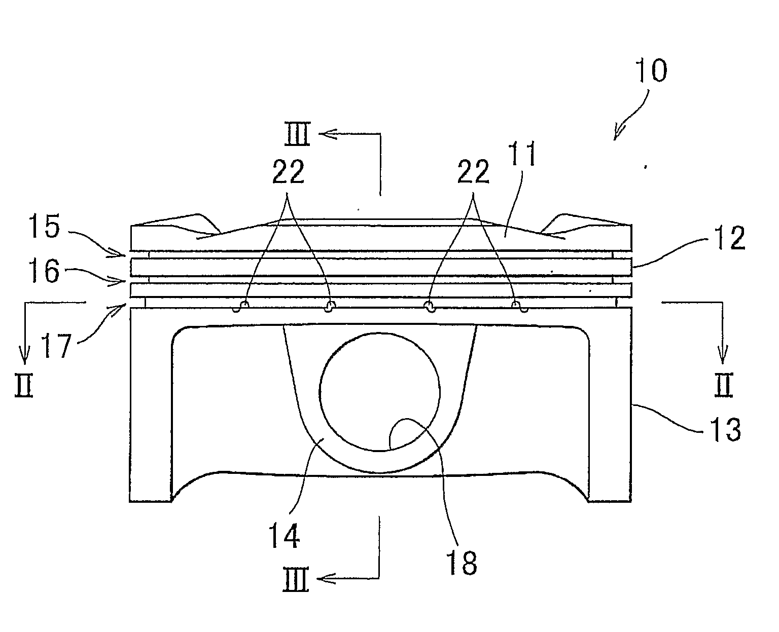
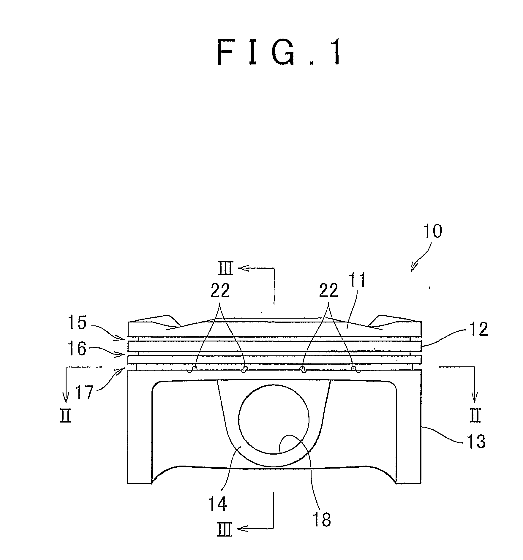
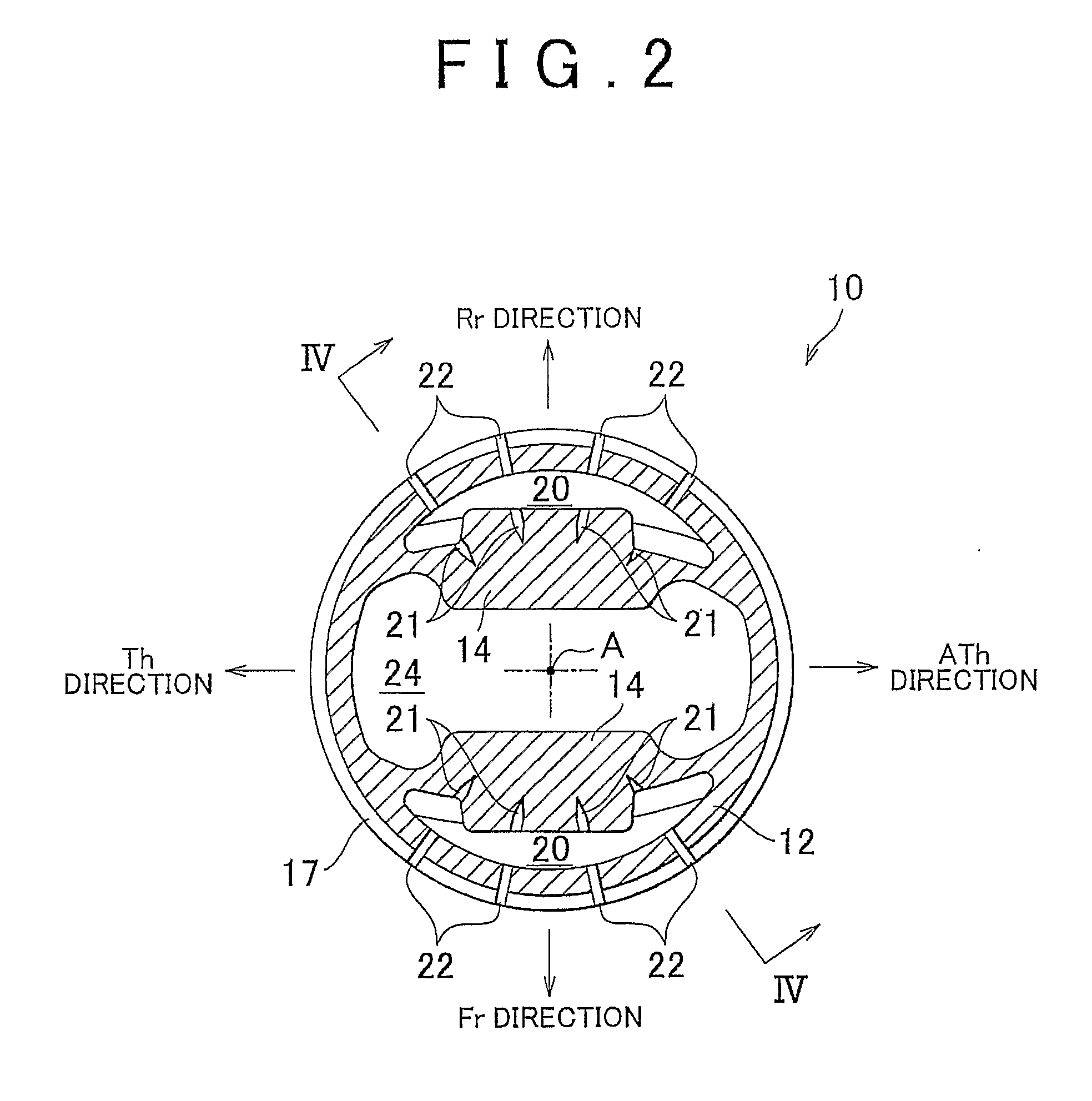
[0025]FIG. 1 is a side view of a piston for an internal combustion engine according to the invention, as viewed from the front (Fr) of the engine. FIG. 2 is a sectional view taken along the line II-II in FIG. 1. FIG. 3 is a sectional view taken along the line III-III in FIG. 1. FIG. 4 is a sectional view taken along the line IV-IV in FIG. 2. As shown in FIG. 2 and others, the direction, in which a piston pin inserted into a piston pin hole extends (the direction in which a crankshaft, connected to the piston through a connecting rod, extends), is designated as forward (Fr) direction and rearward (Rr) direction of the engine.

[0026]The direction perpendicular to the Fr-Rr direction is designated as thrust (Th) direction and anti-thrust (ATh) direction. FIG. 3 shows the piston and an oil jet.

[0027]An internal combustion engine according to the second embodiment of the invention has a piston 10, which will be described later in details, and an oil jet 25 provided below the piston 10.

[00...


PUM


Abstract

A piston (10) for an internal combustion engine including: a piston head (11) located at an uppermost section of the piston; a land (12) located on a circumference of the piston head (11); a skirt (13) located below the land (12); and a pair of pin bosses (14) located on the lower section of the piston head (11). The piston head (11) has a first cavity (24) on the bottom of the piston bead (11). Each of the pair of pin bosses (14) has a second cavity (20) in an outer upper section of the pin boss (14). The pin boss (14) has a through hole (21) that communicably connects the first cavity (24) with the second cavity (20).

Description

BACKGROUND OF THE INVENTION[0001]1. Field of the Invention[0002]The present invention relates to a cooling structure for a piston in an internal combustion engine. The invention also relates to an internal combustion engine provided with the piston having such cooling structure.[0003]2. Description of the Related Art[0004]A piston for an internal combustion engine (hereinafter sometimes simply referred to as “piston”) reciprocates within a cylinder bore when combustion occurs in the engine. Thus, the piston is required to not only be rigid enough to withstand high-speed motions and heat deformation, but also be light and have lubrication and cooling performance. For instance, the related art described in the Japanese Utility Model application publication No. JP-U-7-17937 offers the piston having a reduced weight, and improved lubrication and cooling performance.[0005]The piston described in the Japanese Utility Model application publication No. JP-U-7-17937 has recesses formed in th...

Claims


Application Information

Patent Timeline
Patent Type & Authority Applications(United States)
IPC IPC(8): F02F3/22
CPCF02F3/22F01P3/06
Inventor MATSUI, JUNHAYAMA, KENJI
Owner TOYOTA JIDOSHA KK
Why Eureka
Try Eureka