Electrolyzer and electrodes
- Summary
- Abstract
- Description
- Claims
- Application Information
AI Technical Summary
Benefits of technology
Problems solved by technology
Method used
Image

Examples
embodiment 1
[0040]This embodiment is directed to an instance of an electrode used in an electrolytic hydrogen producing apparatus using an alkaline aqueous solution and also to a method for making same.
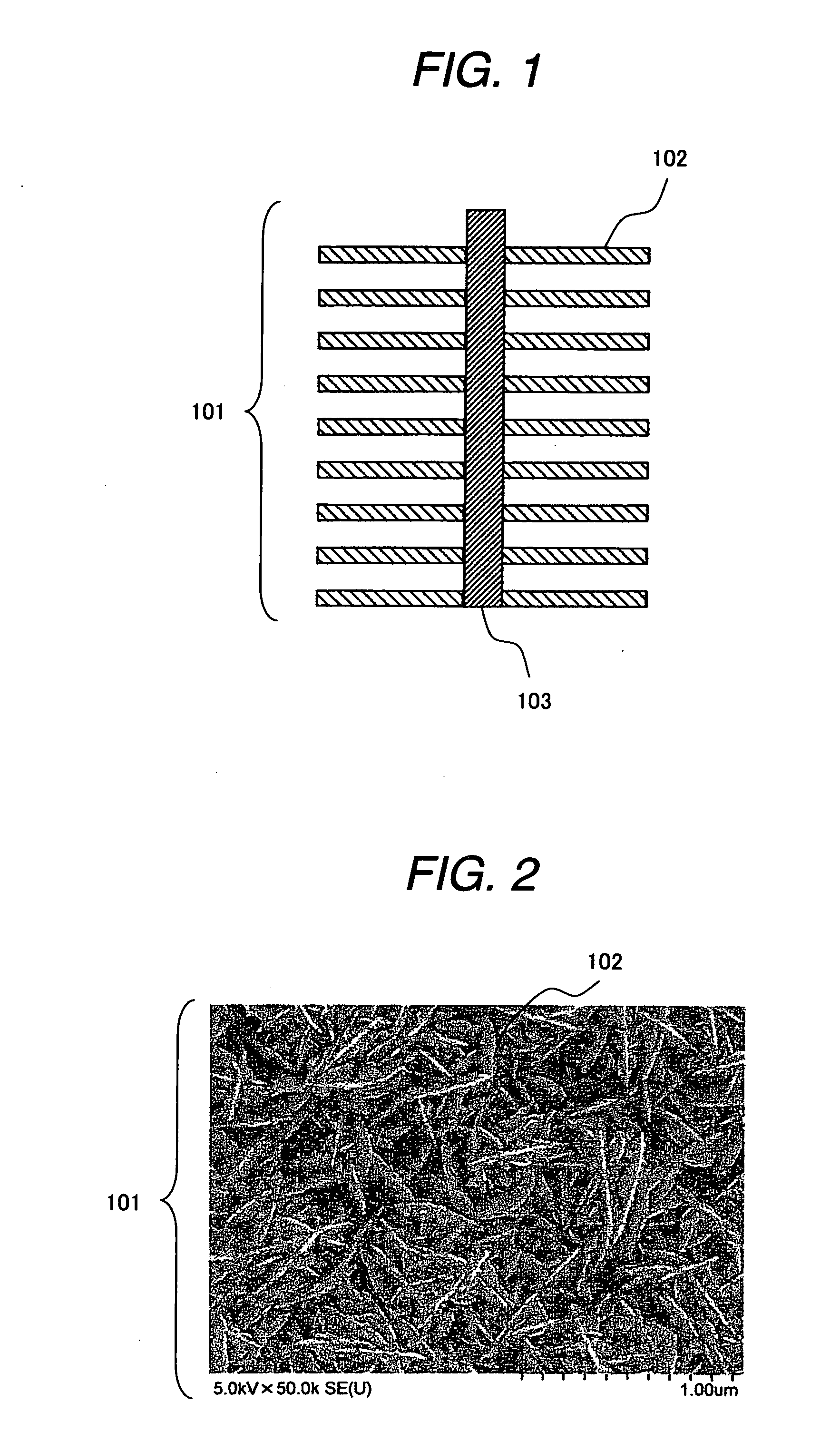
[0041]FIG. 1 is a schematic sectional view showing an instance of an electrode 101 of the invention. The electrode 101 is comprised of prominences 102 and an electrode core 103. The prominences 102 are metal-bonded with the electrode core 103 and each have a leaf-shaped form. Since prominences 102 shown in FIG. 1 are drawn by schematic sectional diagram, the leaf-shaped form thereof is not shown in FIG. 1, but the detail of the leaf-shaped form of the prominences 102 are shown in FIG. 2, and they are described later. The prominences 102 although rises perpendicularly from the electrode core 103 as shown in FIG. 1, they may rises from the electrode 103 with inclination. The sectional structure of each prominence 102 may have a thickness kept constant from the bonded portion with the electrode core...
embodiment 2
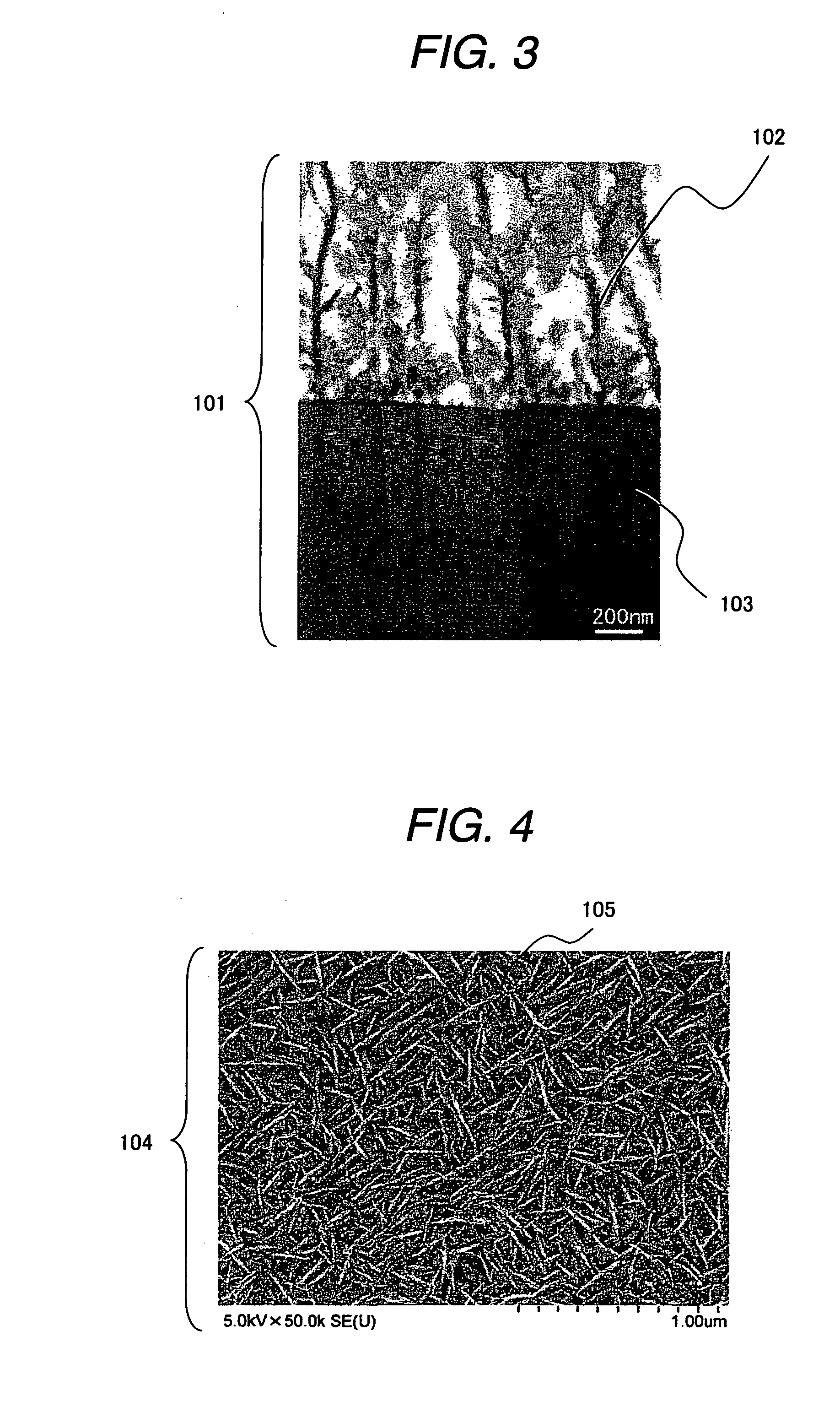
[0046]In Embodiment 2, the electroplating treatment was carried out with conditions that the additive was changed to toluenesulfonic acid (special grade reagent, made by Wako Pure Chemical Industries, Ltd.). The material of the electrode core and electroplating conditions were same as in embodiment 1. FIG. 4 is a surface image of the electrode 104 of this example observed through a scanning electron microscope. Like the electrode 101, it could be confirmed that leaf-shaped prominences 105 were formed. The prominences 105 had a minor-axis length of about 5 to 20 nm and a major-axis length of about 300 to 800 nm. The specific surface area of the electrode measured on the basis of the peak charge amount was 97 times greater than the area of a commercially available Ni sheet (made by The Nilaco Corporation), so that it could be confirmed that the formation of the prominences 105 contributed to an improvement in the specific surface area.
embodiment 3
[0050]In Embodiment 3, a Ni mesh (made by The Nilaco Corporation) was used as an electrode core. The electrolytic conditions were same as in Embodiment 1. The electrode surface obtained after completion of the plating was black in color like Embodiment 1 and no metallic luster was observed. The surface was observed through a scanning electron microscope, from which it could be confirmed that leaf-shaped prominences were irregularly arranged over the entire surface of the electrode like Embodiment 1. The prominences had a minor-axis length of about 30 to 60 nm and a major-axis length of about 300 to 1200 nm.
[0051]In order to confirm the performance of the electrode for a hydrogen producing apparatus, an overvoltage at arbitrary current densities was measured. For the measurement, a three electrode system was used including a nickel mesh (made by The Nilaco Corporation) as a counter electrode and a silver / silver chloride electrode (made by BAS) as a reference electrode. A 1M potassium...
PUM
| Property | Measurement | Unit |
|---|---|---|
| Length | aaaaa | aaaaa |
| Length | aaaaa | aaaaa |
| Length | aaaaa | aaaaa |
Abstract
Description
Claims
Application Information
 - Generate Ideas
- Intellectual Property
- Life Sciences
- Materials
- Tech Scout
- Unparalleled Data Quality
- Higher Quality Content
- 60% Fewer Hallucinations
Browse by: Latest US Patents, China's latest patents, Technical Efficacy Thesaurus, Application Domain, Technology Topic, Popular Technical Reports.
© 2025 PatSnap. All rights reserved.Legal|Privacy policy|Modern Slavery Act Transparency Statement|Sitemap|About US| Contact US: help@patsnap.com