
Method for manufacturing magnetic head

Inactive Publication Date: 2009-06-18
FUJITSU LTD
View PDF4 Cites 10 Cited by
  • Summary
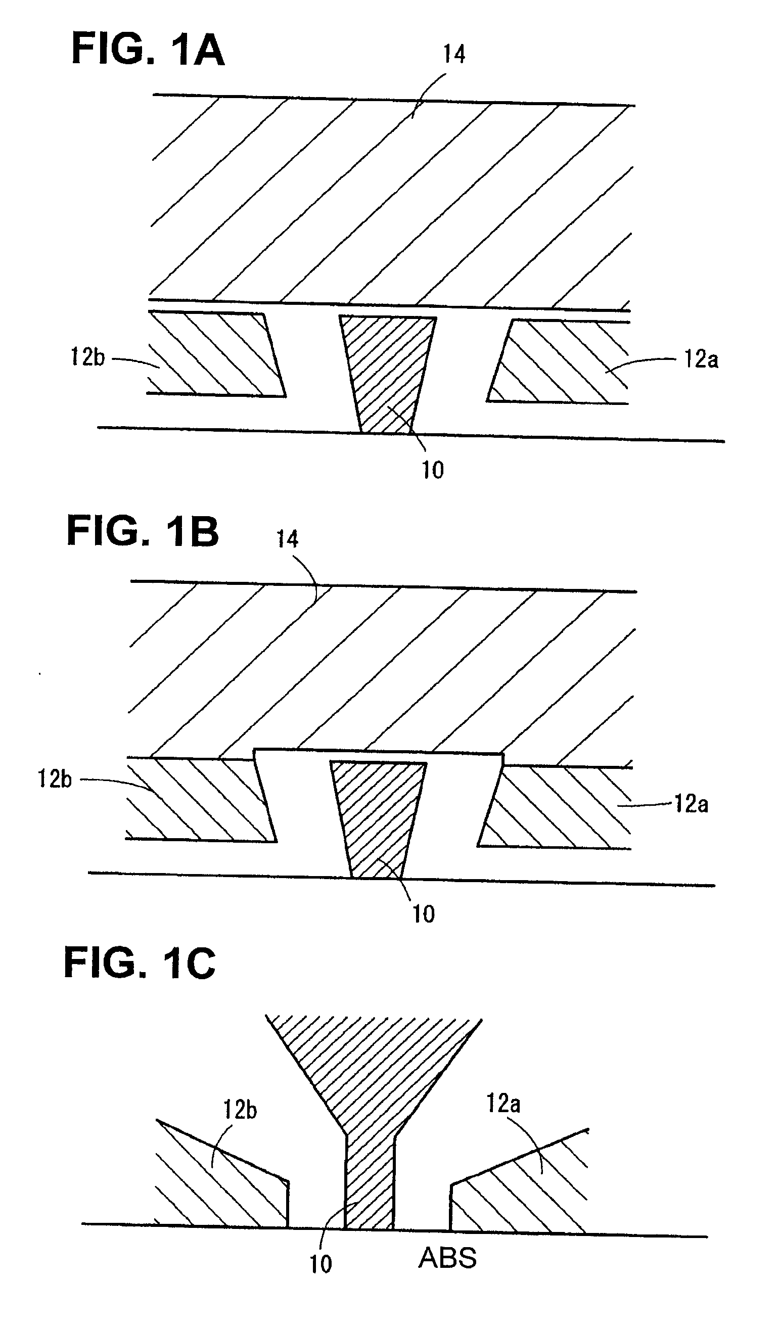
  • Abstract
  • Description
  • Claims
  • Application Information

AI Technical Summary

Benefits of technology

[0008]According to an aspect of an embodiment, a method for manufacturing a magnetic head includes: providing a substrate; forming a first magnetic layer having a pattern for forming a magnetic pole on the substrate; forming a stopper layer of non-magnetic material on the top and the sides of the first magnetic layer; reducing the thickness of the stopper layer on the top of the first magnetic layer; forming a second magnetic layer on the stopper layer; polishing the second magnetic layer to expose the stopper layer on the top of the first magnetic layer; and removing the stopper layer on the top of the first magnetic layer, so as to expose the top of the first magnetic layer.

Problems solved by technology

This causes the so-called side track erase problem that information written in the adjacent track is erased, or that the SN ratio of the magnetic recording is reduced.
As the recording density of recording media is increased, however, the side erase problem becomes noticeably occurring.

Method used


Image

  • Method for manufacturing magnetic head
  • Method for manufacturing magnetic head
  • Method for manufacturing magnetic head

Examples


first embodiment

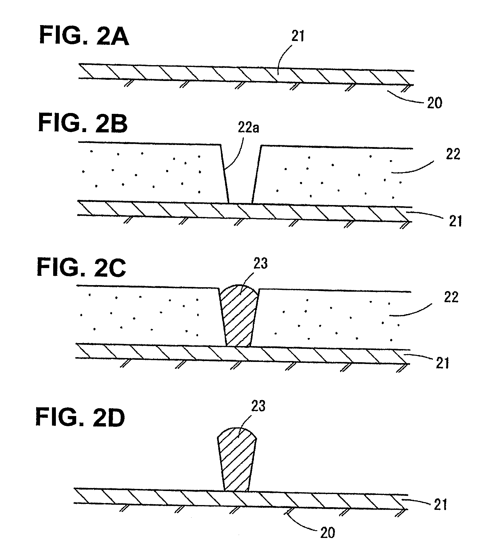
[0023]FIGS. 2A to 5F are representations of a method for manufacturing a magnetic head according to a first embodiment, showing steps for forming a main magnetic pole of a perpendicular magnetic head and side shields disposed with the main magnetic pole in between.

Forming a First Magnetic Layer

[0024]FIGS. 2A to 2D are representation of a process up to the step of forming a first magnetic layer 23 intended for the main magnetic pole on the surface of a substrate. The substrate has a read head including a read element.

[0025]FIG. 2A shows the state in which a plating seed layer 21 has been formed of, for example, ruthenium on a base layer 20 formed on the surface of the substrate by sputtering.

[0026]Then, a resist pattern 22 is formed on the surface of the plating seed layer 21 (FIG. 2B). For forming the resist pattern 22, the surface of the plating seed layer 21 is coated with a resist layer. The resist layer is exposed to light corresponding to a pattern of the main magnetic poles to...

second embodiment

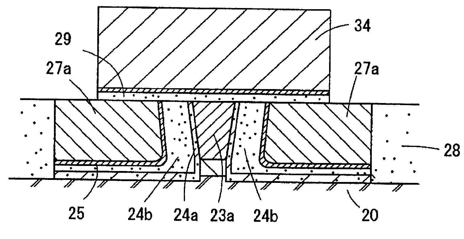
[0068]In the first embodiment, a side gap layer is formed by sputtering a single stopper material after forming the first magnetic layer 23, as shown in FIGS. 3A and 3B, so that the side gap layer can serve as a polishing stopper. In the magnetic head manufacturing method shown in FIGS. 7A to 7F, the stopper layer and the side gap layer are formed of respective materials.

[0069]FIG. 7A shows the state in which a stopper layer 24a has been formed to a thickness sufficient to act as a polishing stopper on the top of the first magnetic layer 23. The stopper layer 24a is formed of a stopper material, such as Ta, by sputtering. The sputtering step deposits the stopper material on the top and side surfaces of the first magnetic layer 23. The thickness of the stopper layer 24a on the sides of the first magnetic layer 23 is smaller than that on the top of the first magnetic layer 23. The stopper layer 24a on the side surfaces of the first magnetic layer 23 defines part of the side gap layer....


PUM

PropertyMeasurementUnit
Thicknessaaaaaaaaaa
Magnetismaaaaaaaaaa
aaaaaaaaaa

Abstract

According to an aspect of an embodiment, a method for manufacturing a magnetic head includes: providing a substrate; forming a first magnetic layer having a pattern for forming a magnetic pole on the substrate; forming a stopper layer of non-magnetic material on the top and the sides of the first magnetic layer; reducing the thickness of the stopper layer on the top of the first magnetic layer; and forming a second magnetic layer on the stopper layer. The method further includes: polishing the second magnetic layer to expose the stopper layer on the top of the first magnetic layer; and removing the stopper layer on the top of the first magnetic layer, so as to expose the top of the first magnetic layer.

Description

CROSS REFERENCE TO RELATED APPLICATIONS[0001]This application is based upon and claims the benefit of priority from the prior Japanese Patent Application No. 2007-322674 filed on Dec. 14, 2007, the entire content of which is incorporated herein by reference.BACKGROUND[0002]1. Field[0003]This art relates to magnetic heads for writing information on recording media.[0004]2. Description of the Related Art[0005]In magnetic heads used in magnetic disk devices, the skew angle is varied depending on whether the arm supporting the magnetic head lies at the inner periphery side or at the outer periphery side of the recording medium.[0006]This causes the so-called side track erase problem that information written in the adjacent track is erased, or that the SN ratio of the magnetic recording is reduced. In order to prevent the side track erase problem, the recording magnetic pole has an inverted trapezoidal end face.[0007]As the recording density of recording media is increased, however, the ...

Claims


Application Information

Patent Timeline
IPC IPC(8): C25D5/02C25D5/52
CPCC25D5/022C25D5/12C25D5/52C23C28/023G11B5/315G11B5/3163G11B5/1278
Inventor TACHIBANA, MASANORIKATO, MASAYAITO, TAKASHIMIYAZAWA, HIROYUKI
Owner FUJITSU LTD
Learn More