Eureka AIR delivers breakthrough ideas for toughest innovation challenges, trusted by R&D personnel around the world.

Integrated acoustic bandgap devices for energy confinement and methods of fabricating same

Active Publication Date: 2009-06-18
RESONANCE SEMICON CORP
View PDF13 Cites 18 Cited by
  • Summary
  • Abstract
  • Description
  • Claims
  • Application Information

AI Technical Summary

Benefits of technology

[0010]In accordance with aspects of the present invention, monolithic devices are provided which include a resonator element that can vibrate, within a certain frequency range, inside an engineered solid. By removing the need for free space vibration in a hermetic enclosure, devices embodying the present invention are effectively immune to shock, vibration and perturbation of the conditions at the surface of the devices. As explained in detail below, design and fabrication of circuit elements with such resonator elements may be done using the same technology as is used for fabricating the driving circuit, thus providing for efficient fabrication.

Problems solved by technology

Otherwise they will not work as intended.
However, unlike quartz crystal oscillators, since MEMS devices are often fabricated on silicon wafers, the hermetic cavity is commonly produced on this wafer rather than on the package.
The creation of such cavities often requires delicate and expensive assembly processes.
Further, cavities pose additional challenge for making the necessary electrical connection to the oscillator devices.
Unfortunately, by their fragile nature the aforementioned free space devices are sensitive to vibration that degrades their performance or shock that can destroy them.
Such free space devices are subject to a force when experiencing acceleration.
The fact that such devices are free to move makes them very sensitive to the aforementioned effects.

Method used


Image

  • Integrated acoustic bandgap devices for energy confinement and methods of fabricating same
  • Integrated acoustic bandgap devices for energy confinement and methods of fabricating same
  • Integrated acoustic bandgap devices for energy confinement and methods of fabricating same

Examples


Embodiment Construction

[0027]The invention is described in terms of several embodiments. These embodiments are described in terms of an oscillator element that contains a resonant structure referred to as a resonant element.

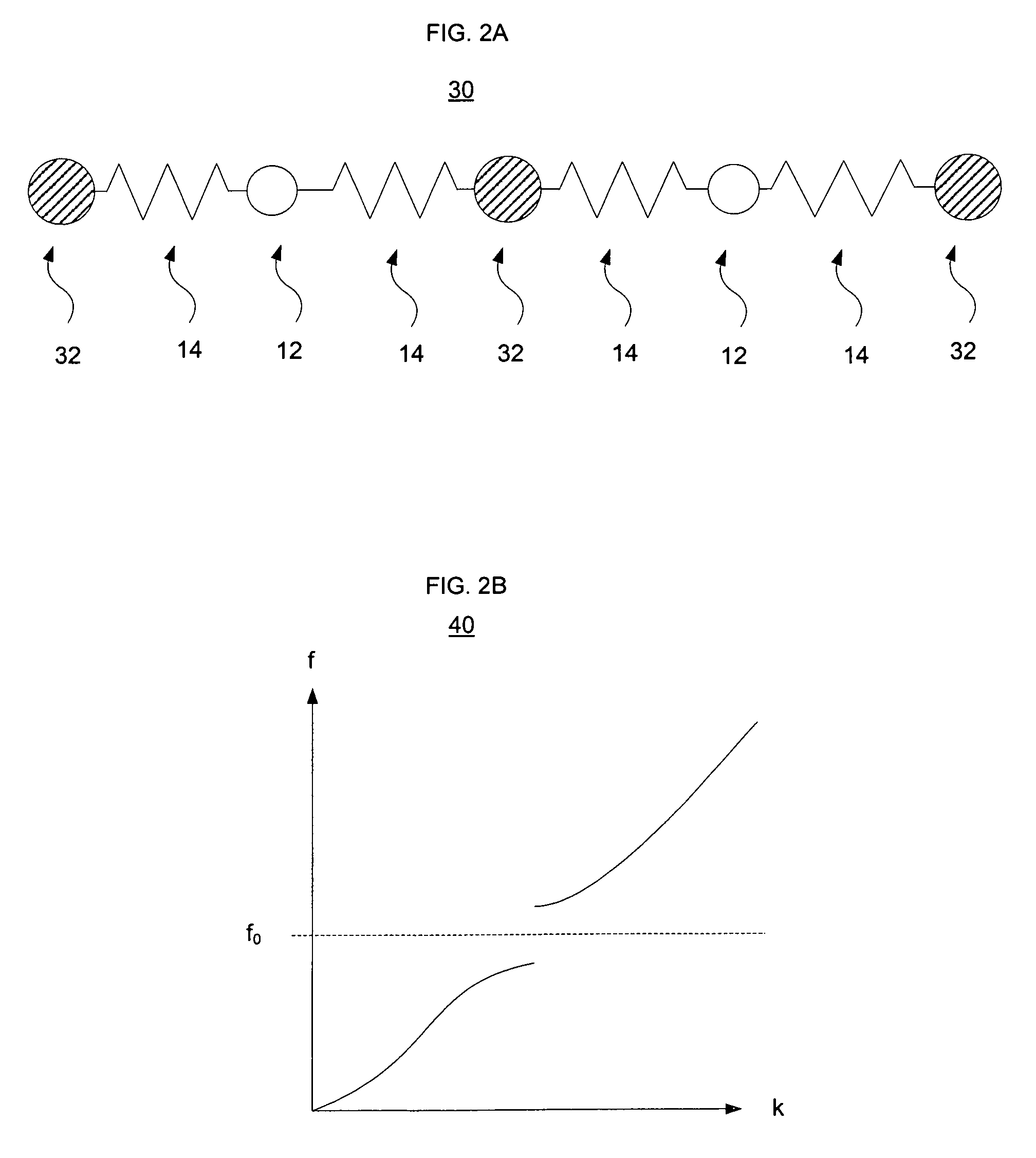
[0028]As explained above, quartz crystal and MEMS oscillators may be unsuitable in various applications due to their fragile structures. In accordance with certain aspects of the present invention, such deficiencies may be overcome by employing monolithic integrated circuits configured for use in timing and related applications. In particular, materials are employed so that vibrations of a certain frequency or range of frequencies cannot propagate across them. Such materials can be said to have a band-gap at a given frequency or frequencies.

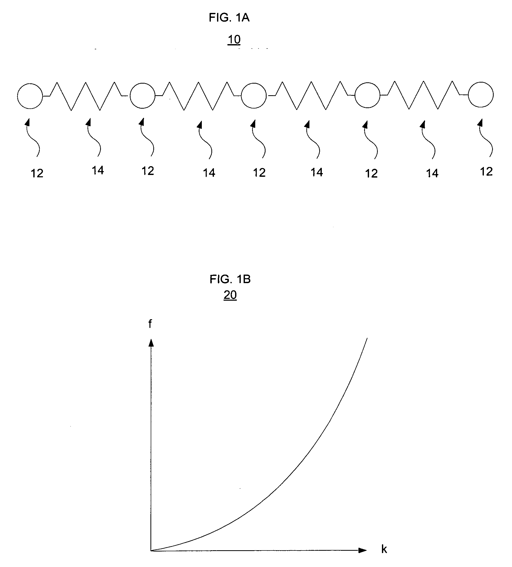
[0029]In order to understand how materials and devices of the present invention function, it is useful to consider a number of idealized cases. First, the exemplary structure 10 of FIG. 1A presents a linear chain of particles 12 of the same mass tha...


PUM

PropertyMeasurementUnit
Fractionaaaaaaaaaa
Temperatureaaaaaaaaaa
Thicknessaaaaaaaaaa

Abstract

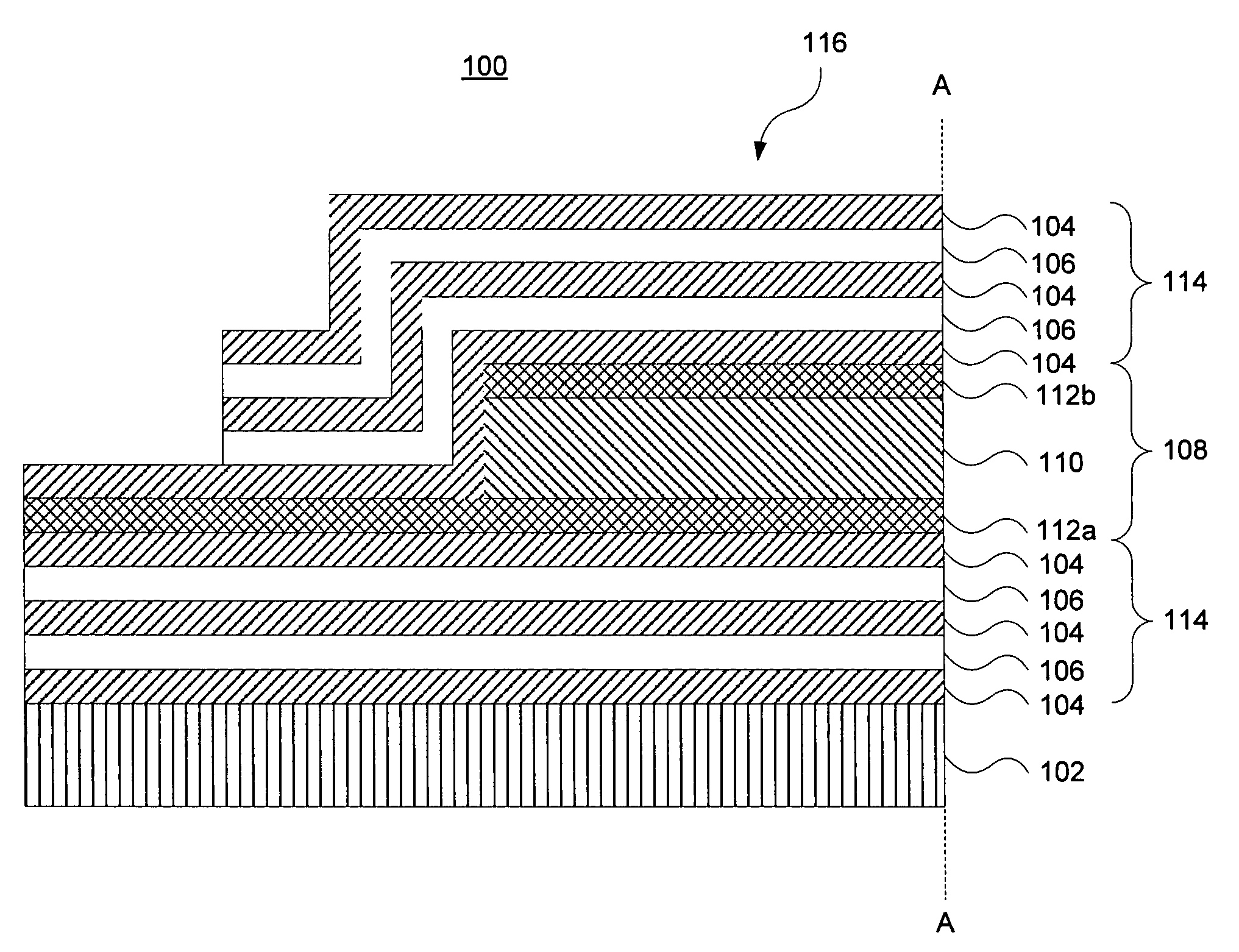
The present invention is directed to monolithic integrated circuits incorporating an oscillator element that is particularly suited for use in timing applications. The oscillator element includes a resonator element having a piezoelectric material disposed between a pair of electrodes. The oscillator element also includes an acoustic confinement structure that may be disposed on either side of the resonator element. The acoustic confinement element includes alternating sets of low and high acoustic impedance materials. A temperature compensation layer may be disposed between the piezoelectric material and at least one of the electrodes. The oscillator element is monolithically integrated with an integrated circuit element through an interconnection. The oscillator element and the integrated circuit element may be fabricated sequentially or concurrently.

Description

BACKGROUND OF THE INVENTION[0001]The present invention provides monolithic integrated circuits that are particularly adapted for use in timing applications, as well as methods for designing and fabricating same.[0002]Conventional electronic appliances include a timing unit to provide a timing base that controls the internal functioning of the appliance as well as communications with other appliances or devices. Such timing units often comprise a resonator and a driving circuit. In many cases the resonator and circuit are fabricated using different technologies, and thus need wiring or other manner of interconnection in order to function together.[0003]Typically, the resonator is a piezoelectric device that vibrates in free space. The most common resonator is a quartz crystal oscillator that when driven at one of its mechanical resonant frequencies has either a minimum or maximum in its electrical impedance, which is used by the driving circuit to lock itself at this frequency value....

Claims


Application Information

Patent Timeline
IPC IPC(8): H03H9/15H03H3/02
CPCH03H9/589H01L27/02H03H9/0557H03H9/175H03H9/564Y10T29/42H03H9/0538H03H9/17
Inventor SINHA, RAJARISHIGAMMEL, PETER LEDELMASTRAPASQUA, MARCOSAFAR, HUGO
Owner RESONANCE SEMICON CORP
Why Eureka
Eureka Blog
Learn More