Multilayer capacitor

Active Publication Date: 2009-06-18
MURATA MFG CO LTD
View PDF19 Cites 63 Cited by
  • Summary
  • Abstract
  • Description
  • Claims
  • Application Information

AI Technical Summary

Benefits of technology

[0019]To overcome the problems described above, preferred embodiments of the present invention provide a mul

Problems solved by technology

If voltage in a power supply line varies significantly due to an impedance between the power supply line and a ground, the voltage variation may cause the operation of a driven circuit to be unstable, cause inter-circuit interference via the power supply circuit, and generate an oscillation.
Therefore, noise including greater amounts of higher harmonic components is more likely to occur, and an IC power supply circuit requires stronger decoupling.
If dV has a large value, supply of the charge to the IC is delayed.
It is, however, known that if the ESR of the capacitor becomes too low, an impedance mismatch is caused in a circuit, and a damped oscillation, called “ringing”, to distort the rising of a signal waveform is more likely to occur.
The occurrence of the ringing may cause a malfunction of the IC due to a distorted signal.
In addition, if the ESR of the capacitor becomes too low, an impedance-frequency char

Method used


Image

  • Multilayer capacitor
  • Multilayer capacitor
  • Multilayer capacitor

Examples


Embodiment Construction

[0074]A first preferred embodiment of the present invention will be described below with reference to FIGS. 1 to 4B. The first preferred embodiment and second to ninth preferred embodiments that will be described later are in accordance with the first aspect of the present invention.

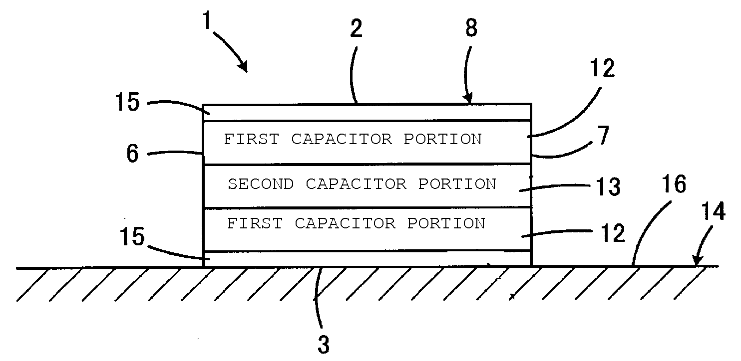
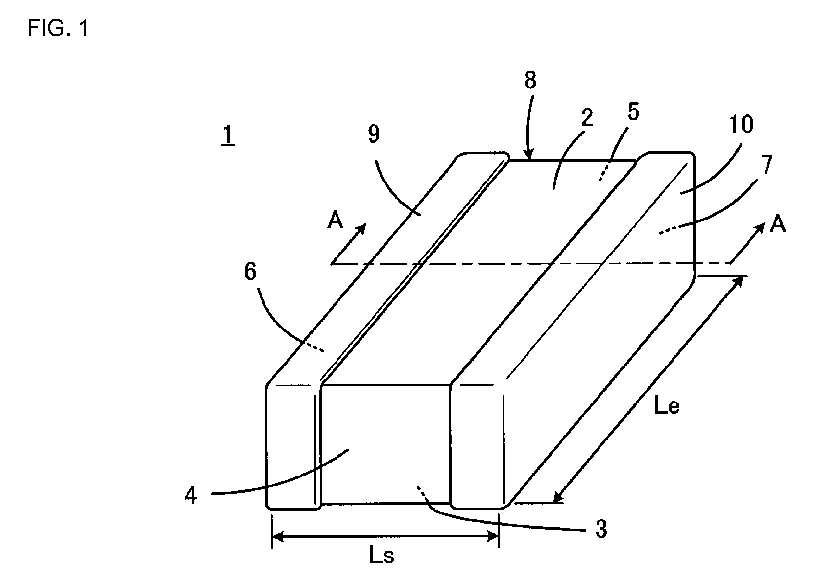
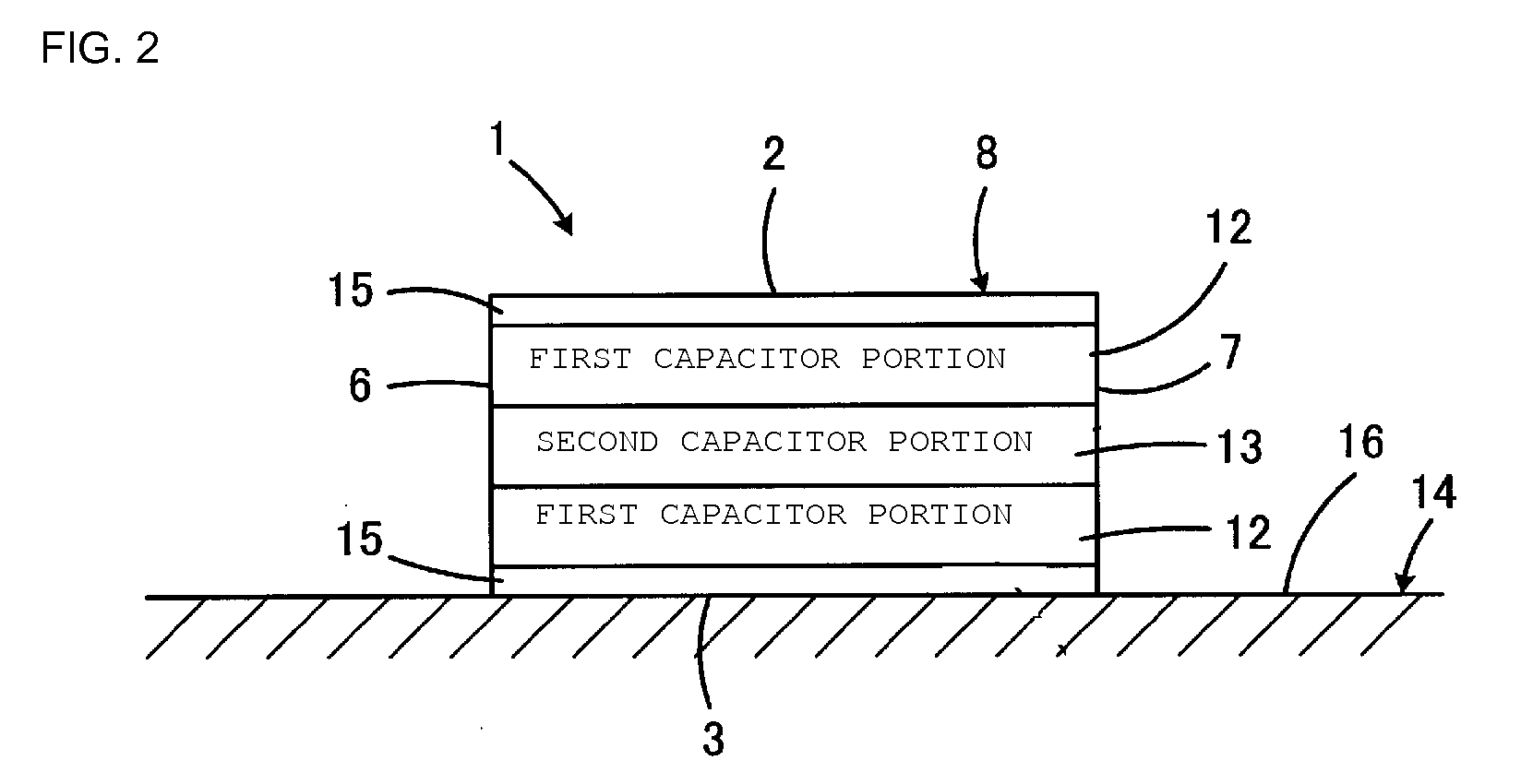
[0075]FIG. 1 is a perspective view showing an external appearance of a multilayer capacitor 1 according to the first preferred embodiment. The multilayer capacitor 1 includes a capacitor body 8 preferably having a substantially rectangular parallelepiped shape, for example, having a first principal surface 2 and a second principal surface 3 opposed to each other, a first side surface 4 and a second side surface 5 opposed to each other, and a first end surface 6 and a second end surface 7 opposed to each other. The multilayer capacitor 1 preferably is a LW-reversed type multilayer capacitor in which a length Le of the first and second end surfaces 6 and 7 is greater than a length Ls of the first and secon...


PUM


Abstract

In a capacitor body of a multilayer capacitor, one second capacitor portion is sandwiched between two first capacitor portions. An ESR is controlled by setting a width of lead portions of third and fourth internal electrodes disposed in the second capacitor portion to be less than that of lead portions of first and second internal electrodes disposed in the first capacitor portions and by changing ratios between the first and second capacitor portions in the width of the lead portions and in the number of stacked internal electrodes. In the first capacitor portions, current paths from the internal electrodes to an external terminal electrode are widely distributed so that the first capacitor portions have a relatively low ESL, and accordingly, the ESL of the entire multilayer capacitor is reduced.

Description

BACKGROUND OF THE INVENTION[0001]1. Field of the Invention[0002]The present invention relates to a multilayer capacitor, and more particularly, to an improvement to facilitate control of an equivalent series resistance (ESR) of the multilayer capacitor.[0003]2. Description of Related Art[0004]If voltage in a power supply line varies significantly due to an impedance between the power supply line and a ground, the voltage variation may cause the operation of a driven circuit to be unstable, cause inter-circuit interference via the power supply circuit, and generate an oscillation. To avoid these problems, a decoupling capacitor is usually connected between the power supply line and the ground. The decoupling capacitor reduces the impedance between the power supply line and the ground, and suppresses variations of the power supply voltage and the inter-circuit interference.[0005]Recently, in communication equipment, such as cell-phones, for example, and information processing equipmen...

Claims


Application Information

Patent Timeline
IPC IPC(8): H01G4/30
CPCH01G4/30H01G4/228
Inventor TAKASHIMA, HIROKAZUUEOKA, HIROSHITAKAGI, YOSHIKAZU
Owner MURATA MFG CO LTD
Why Eureka
Try Eureka