Wavelength-selective light-shielding element and optical head using the same

a technology of which is applied in the field of wavelength-selective light shielding element and optical head using the same, can solve the problems of unavoidable deterioration of reproduction accuracy, and decrease in light utilization ratio, so as to improve the utilization ratio of ligh

Inactive Publication Date: 2009-06-18
ASAHI GLASS CO LTD
View PDF7 Cites 5 Cited by
  • Summary
  • Abstract
  • Description
  • Claims
  • Application Information

AI Technical Summary

Benefits of technology

[0014]Accordingly, the present invention aims at providing a wavelength-selective light-shielding element that prevents occurrence of interference when prevention of interference between information light and stray light is required and that enables enhancement of a utilization ratio of light when prevention of interference is not required, as well as providing an optical head using the element.
[0052]By means of the configuration, enhancement of the ratio of utilization of light is achieved in the case of reproduction of data from one recording layer, as well as occurrence of interference between information light and stray light, which would otherwise be caused when data are reproduced form a plurality of recording layers, is prevented.
[0053]As mentioned above, according to the present invention, there is provided a light-shielding region that permits passage of the first circularly-polarized light rotating in a first direction regardless of the wavelength of the first circularly-polarized light and that blocks, among second circularly-polarized light beams rotating in a second direction opposite the first direction, second circularly-polarized light beams whose wavelengths falling within a predetermined range, to thus permit passage of the second circularly-polarized light beams falling outside the predetermined range. As a result, there can be provided a wavelength-selective light-shielding element yielding an advantage of the ability to block light beams which rotate in a specific direction and whose wavelengths fall within a specific range as well as an optical head using the wavelength-selective light-shielding element.

Problems solved by technology

Therefore, interference between the information light and the stray light sometimes leads to deterioration of the accuracy of reproduction.
Consequently, the information light reflected from the reproduction layer and the stray light reflected from the non-reproduction layer interfere with each other within the photodetector 805; hence, deterioration of the accuracy of reproduction is unavoidable.
When an optical disk (e.g., a CD) having a single recording layer which does not require prevention of interference is subjected to reproduction, information light that has a high density of light and that is acquired in the vicinity of an optical axis is lost, which raises a problem of a decrease in a utilization ratio of light.

Method used


Image

  • Wavelength-selective light-shielding element and optical head using the same
  • Wavelength-selective light-shielding element and optical head using the same
  • Wavelength-selective light-shielding element and optical head using the same

Examples


first embodiment

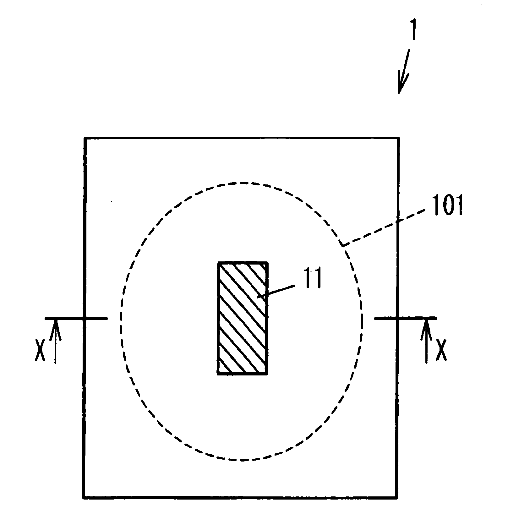
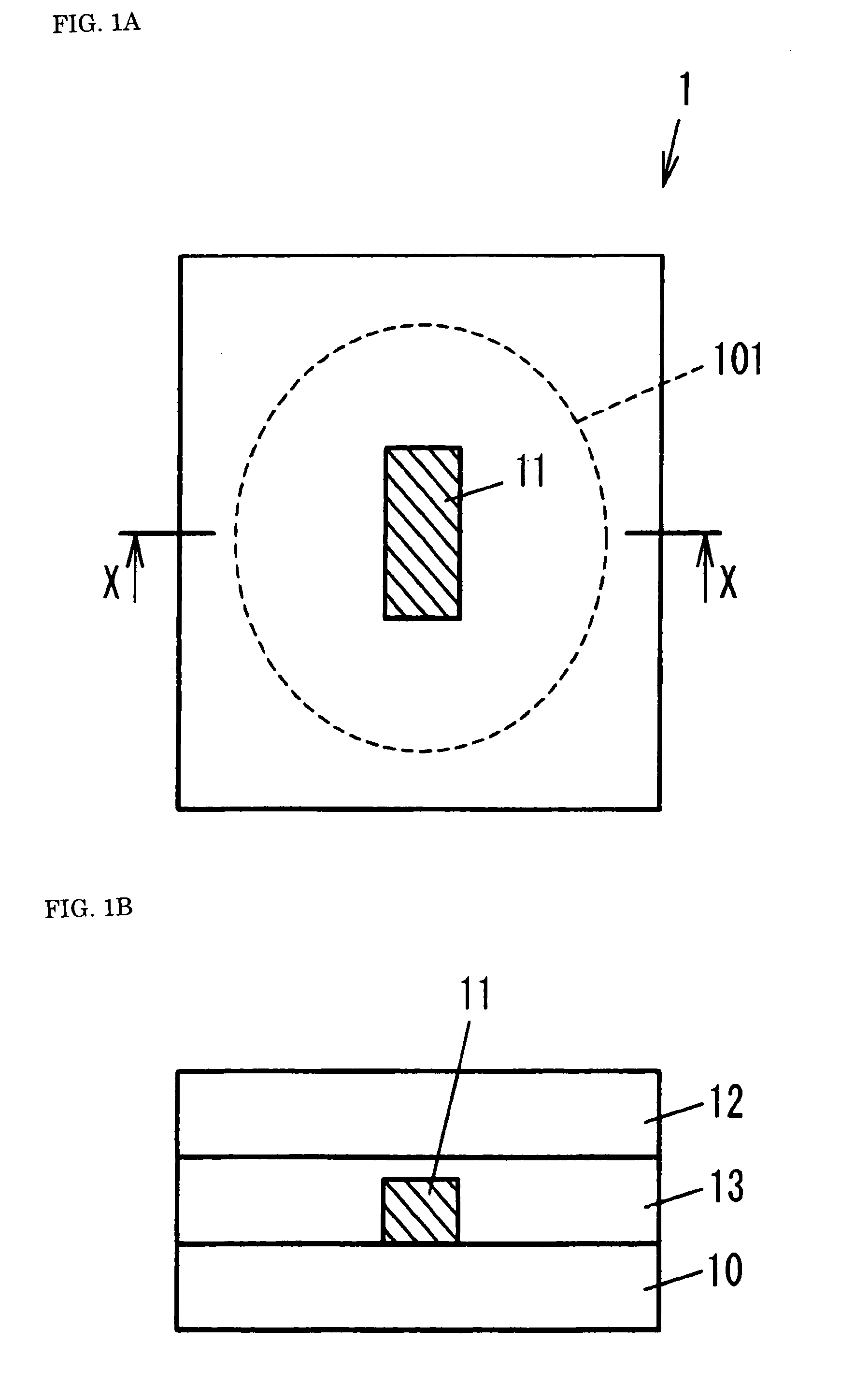
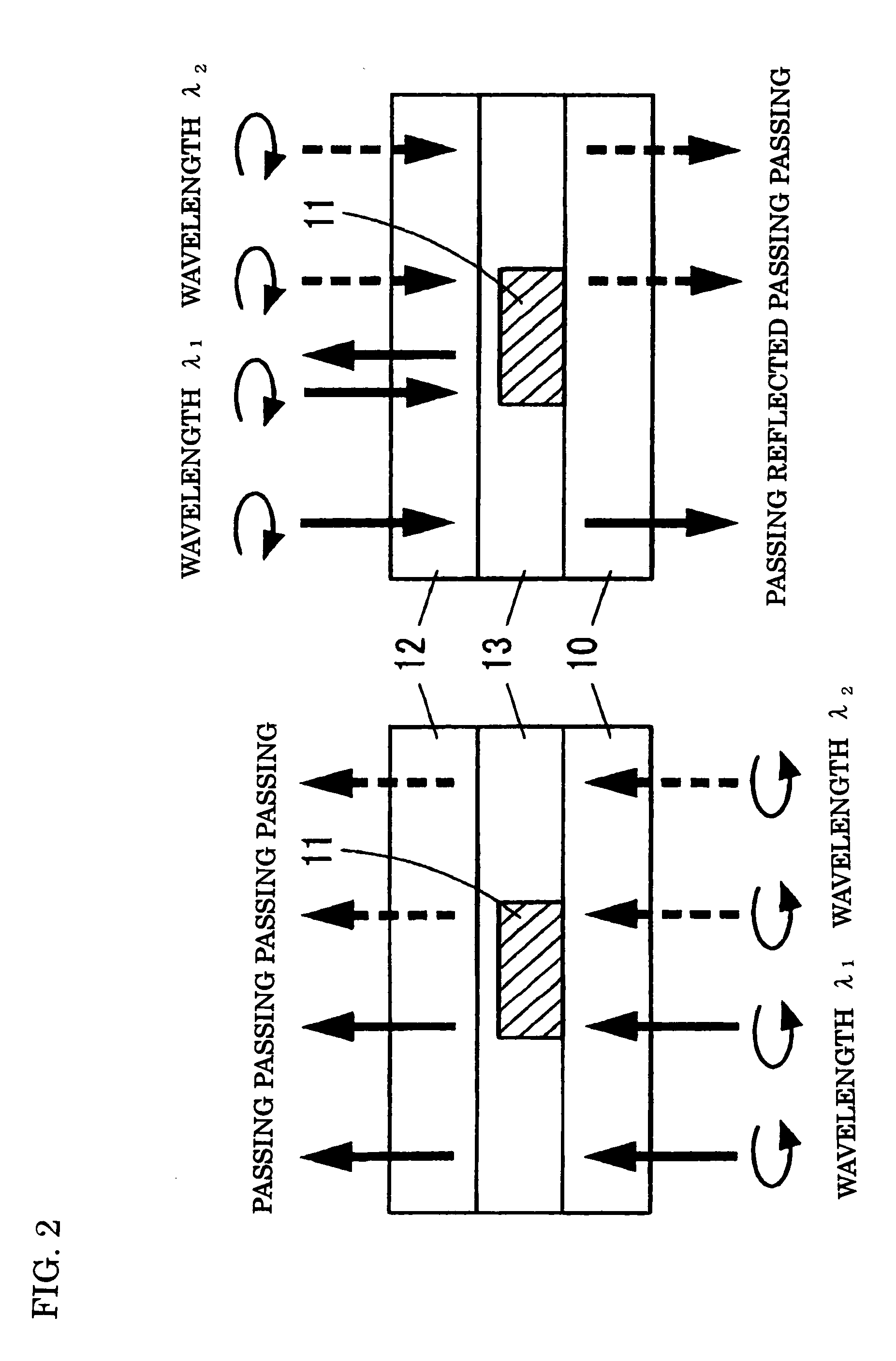
[0069]As shown in FIGS. 1A and 1B, a wavelength-selective light-shielding element 1 of the present invention has at least one light-shielding region 11 provided in a part of a transparent substrate 10 where light passes through an effective region 101. The light-shielding region 11 permits passage of first circularly-polarized light that rotates in a first direction (e.g., a counterclockwise direction) regardless of its wavelength; blocks second circularly-polarized light beams whose wavelength fall within a predetermined range of second circularly-polarized light that rotates in a second direction (e.g., a clockwise direction); and permits passage of second circularly-polarized light beams falling outside the predetermined range.

[0070]Specifically, the wavelength-selective light-shielding element 1 is built from two transparent substrates 10 and 12; cholesteric phase liquid crystal that is formed over the transparent substrate 10 and that functions as a light-shielding region 11; a...

second embodiment

[0111]the present invention will now be described.

[0112]As shown in FIG. 5A, the wavelength-selective light-shielding element 5 of the present embodiment uses, as a light-shielding region 51, a wavelength-selective diffraction grating made of cholesteric phase liquid crystal. Since the characteristic of transmission diffraction of the cholesteric phase liquid crystal is used in the present embodiment, the wavelength λ of light handled by the wavelength-selective light-shielding element 5 of the second embodiment preferably falls outside a reflection wavelength band that is equal to or less than λc−Δλ / 2 or equal to or greater than λc+Δλ / 2.

[0113]In relation to light whose wavelength is in close vicinity to the reflection wavelength band, the wavelength-selective diffraction grating made of cholesteric phase liquid crystal undergoes an increase in difference between a refractive index of circularly-polarized light that rotates in the same direction as the direction of rotation of the c...

third embodiment

[0133]the present invention will now be described.

[0134]As shown in FIG. 6A, a wavelength-selective light-shielding element 6 of a present embodiment is identical with its counterpart described in connection with the second embodiment in that a first wavelength-selective diffraction grating 61 produced from cholesteric phase liquid crystal is used as a light-shielding area; however, the present embodiment differs from the second embodiment in that a second wavelength-selective diffraction grating 62 whose grid pitch is wider than that of the first wavelength-selective diffraction grating 61 is formed outside the first wavelength-selective diffraction grating 61.

[0135]As shown in FIG. 6B, the wavelength-selective light-shielding element 6 permits passage of counterclockwise circularly-polarized light but diffracts clockwise circularly-polarized light at a large angle by means of the first wavelength-selective diffraction grating 61 and at a small angle by means of the second waveleng...


PUM

PropertyMeasurementUnit
transparentaaaaaaaaaa
wavelengthaaaaaaaaaa
reflection wavelengthaaaaaaaaaa

Abstract

In order to provide a wavelength-selective light-shielding element capable of blocking circularly-polarized light beams rotating in a specific direction among light beams whose wavelengths falling in a specific range, a light-shielding region is provided in a portion of a transparent substrate, wherein the light-shielding region permits passage of first circularly-polarized light rotating in a first direction regardless of a wavelength of the first circularly-polarized light and blocks second circularly-polarized light beams whose wavelengths falling within a predetermined range, among second circularly-polarized light beams rotating in the second direction, to thus permit passage of the second circularly-polarized light beams falling outside the predetermined range.

Description

TECHNICAL FIELD[0001]The present invention relates to a light-shielding element and an optical head using the same, and more particularly, a wavelength-selective light-shielding element capable of blocking circularly-polarized light beams rotating in a specific direction among light beams in a specific wavelength range as well as to an optical head using the element.BACKGROUND ART[0002]In addition to an optical disk having a single recording layer as in a CD, a multilayer optical disk having a plurality of recording layers for increasing recording capacity as in a DVD and a high-density DVD has come to be used. However, when information is read (hereinafter called “reproduced”) from a recording layer of the multilayer optical disk, stray light reflected from a recording layer not to be subjected to reproduction (a non-reproduction layer) as well as information light reflected from a recording layer to be subjected to reproduction (a reproduction layer) enter a photodetector. Therefo...

Claims


Application Information

Patent Timeline
Patent Type & Authority Applications(United States)
IPC IPC(8): G11B7/00G11B7/13G11B7/135
CPCG02B5/3083G02B27/283G11B2007/0013G11B7/1353G11B7/1381G11B7/131G11B7/1369
Inventor SATO, HIROMASA
Owner ASAHI GLASS CO LTD
Why Eureka
Try Eureka