Qr decomposition apparatus and method for MIMO system

Inactive Publication Date: 2009-06-18
ELECTRONICS & TELECOMM RES INST
1 Cites 13 Cited by

AI-Extracted Technical Summary

Problems solved by technology

In a wireless channel environment having multi-paths, delay spread occurs due to the multiple paths.
If delay spread time is longer than a symbol transmission interval, inter-symbol interference is caused.
However, complexity of the equalizer increases as a data transmission rate increases.
However, the described...

Benefits of technology

[0026]An embodiment of the present invention is directed to providing a QR decomposition apparatus and method for a Multiple...

Abstract

Provided are a QR decomposition apparatus and method for a MIMO system. The QR decomposition apparatus includes: a norm calculator for calculating a vector size norm for a channel input; a Q column calculator for calculating a column value of a unitary matrix Q by multiplying a delayed channel input with √{square root over (norm)}; an R row calculator for receiving the delayed channel input, the output of the Q column calculator, and 1/√{square root over (norm)}, and calculating a row value of an upper triangular matrix R; a Q update calculator for receiving the delayed channel input, the output of the R row calculator, and a delayed output of the Q column calculator, and calculating a Q update matrix value; and a norm update calculator for receiving a delayed output of the norm calculator and an output of the R row calculator, and outputting a norm update matrix value.

Application Domain

Modulated-carrier systemsRadio transmission +3

Technology Topic

Vector sizeCalculator +5

Image

  • Qr decomposition apparatus and method for MIMO system
  • Qr decomposition apparatus and method for MIMO system
  • Qr decomposition apparatus and method for MIMO system

Examples

  • Experimental program(1)

Example

[0049]The advantages, features and aspects of the invention will become apparent from the following description of the embodiments with reference to the accompanying drawings, which is set forth hereinafter.
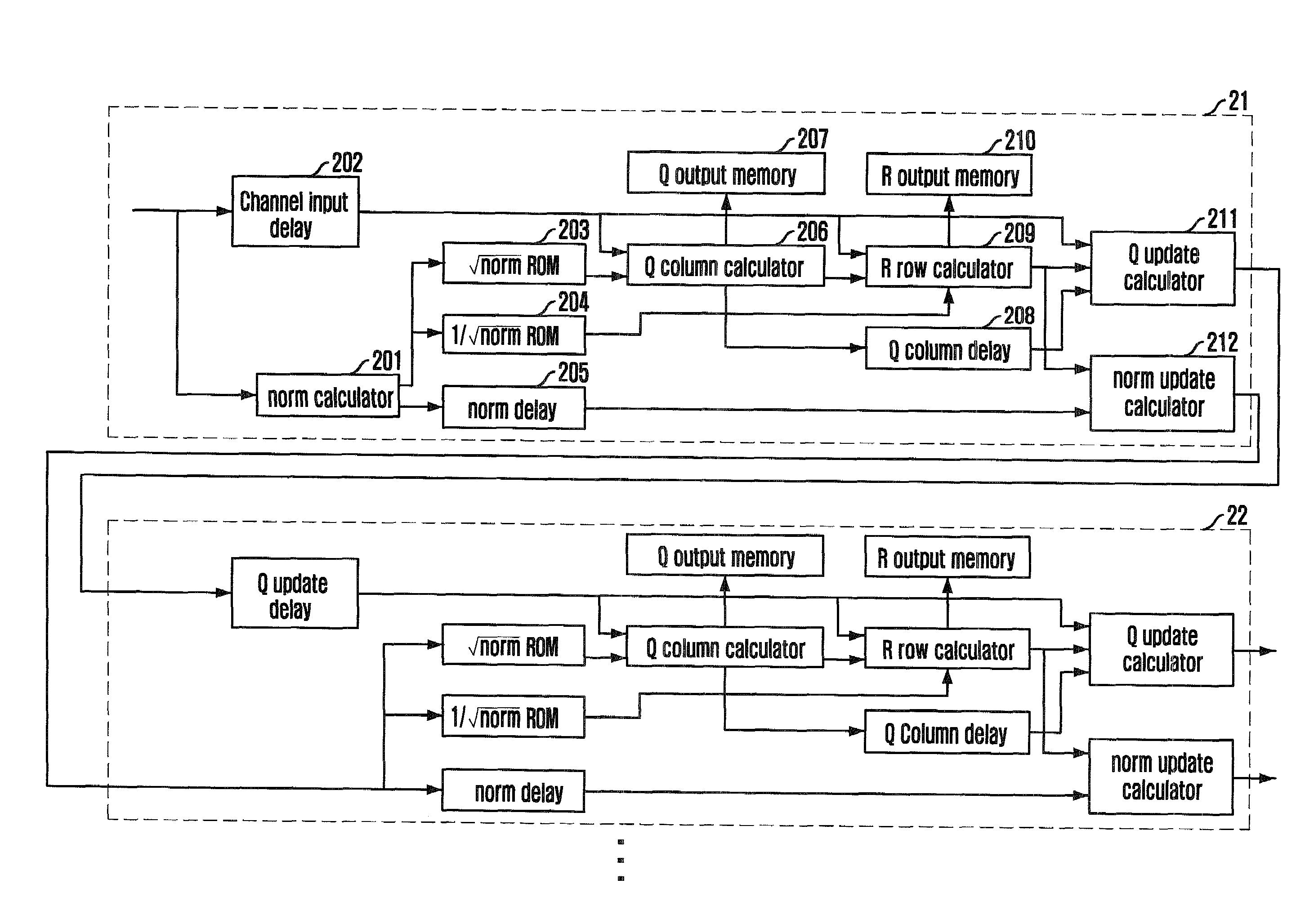
[0050]FIG. 2 is a block diagram illustrating a QR decomposition apparatus in accordance with an embodiment of the present invention.
[0051]Referring to FIG. 2, the QR decomposition apparatus according to the present embodiment includes a norm calculator 201, a channel input delay 202, lookup table ROMs 203 and 204, a norm delay 205, a Q column calculator 206, a Q output memory 207, a Q column delay 208, an R row calculator 209, an R output memory 210, a Q update calculator 211, and a norm update calculator.
[0052]The norm calculator 201 receives channel input after Fast Fourier Transform (FFT) and calculates a vector size norm for qi through normi=|qi|2. The channel input delay 202 delays the channel input qi in order to use the channel input for calculating a column value of a unitary matrix Q and a row value of an upper triangular matrix R.
[0053]The output of the norm calculator 21 is inputted to the lookup table ROMs 203 and 204. Each of the lookup table ROMs 203 and 204 outputs √{square root over (norm)} and 1/√{square root over (norm)} through operation ri,j√{square root over (normi)}. The norm delay 205 delays the output of the norm calculator 201 for updating a norm value to be used at next stage.
[0054]The Q column calculator 206 receives the output value of the lookup table ROM 230 and the delayed qi from the channel input delay 202, performs qi:=qi/ri,j, and outputs a column value of the unitary matrix Q. Hereinafter, a Q column value refers to the column value of the unitary matrix Q.
[0055]Since the calculated Q column value from the Q column calculator 206 is a result value of a QR matrix used for decoding a signal received through multiple antennas, the calculated column value is stored in the Q output memory 207. Also, the calculated column value qi from the Q column calculator 206 is inputted to the Q column delay 208 and delayed to be used for updating the unitary matrix Q at a next stage.
[0056]The R row calculator 209 receives the calculated Q column value from the Q column calculator 206, the delayed channel input from the channel input delay 202, and 1/√{square root over (norm)} from the lookup table ROM 204, and calculates a row value of the upper triangular matrix R through operation ri,jqiHsqk. Hereinafter, a row value of the upper triangular matrix R refers to an R row value. The output value 1/√{square root over (norm)} from the ROM 204 is used as a diagonal value of an R row. Since the calculated row value (ri,j) of the upper triangular matrix R is the first row value of the upper triangle matrix R in the QR decomposition, it is stored in the R output memory 210.
[0057]The Q update calculator 211 receives the delayed value from the channel input delay 202, the delayed Q column value from the Q column delay, and the calculated R row value from the R row calculator, and updates a Q value through operation qk:=qk−ri,j×qi.
[0058]The norm update calculator 212 receives the delayed norm value from the norm delay 205, receives the calculated R row value from the R row calculator, and calculates a norm value through operation normk:=normk−ri,k2.
[0059]In a wireless communication system using multiple antennas, a QR decomposition value from the second antenna is calculated through the same processes as described above. Therefore, the output value of the Q update calculator 211 is inputted to a Q update delay of the next stage 22, and the output value of the norm update calculator 212 is inputted to lookup table ROMS at the next stage 22 for calculating √{square root over (norm)} and 1/√{square root over (norm)}.
[0060]FIG. 3 is an exemplary block diagram illustrating a Q column calculator for describing a floating point number processing method in accordance with an embodiment of the present invention.
[0061]The QR decomposition is performed through multipliers of many stages and the output of the multipliers need the large number of bits constantly. Therefore, a floating point number processing method is used in the present embodiment instead of using a fixed point number processing method. That is, each of the delayed channel input and the calculated channel input has a value of a fixed point number. If the fixed point number is applied to a multiplier as it is, the number of bits increases too much. It could be heavy burden on hardware.
[0062]In order to overcome the problem, the fixed to floating point number converter 301 and 302 and a floating to fixed point number converter 305 are adapted in the present embodiment as shown in FIG. 3. The fixed to floating point number converters 301 and 302 classify a fixed point input value into a significant value and an exponent value.
[0063]The multiplier 303 performs multiplication only with the significant value, and the adder 304 adds the exponent value. Then, the floating to fixed point number converter 305 converts the output of the multiplier 303 and the adder 304 into a fixed point value. As described above, the hardware burden is reduced by reducing the number of bits used in the multiplier using the floating point number processing method.
[0064]FIGS. 4 and 5 are flowcharts describing a method for converting a fixed point number to floating point number and a method for converting a floating point number to a fixed point number in accordance with an embodiment of the present invention.
[0065]At first, a process for converting a fixed point number to a floating point number will be described with reference to FIG. 4.
[0066]The fixed to floating point number converter receives a fixed point type of 21-bits data r. Then, it is determined whether the data r is smaller than 210 and larger than −210 at step S401. If the data r is smaller than 210 and larger than −210, 0-bit is cut from a significant value and the exponent value is set to 0 at step S402.
[0067]If the data r is smaller than 212 and larger than −212 at step s403, 2 bits are cut from the significant value and the exponent value is set as 1 at step S404. Also, if the data r is smaller than 214 and larger than −214 at step S405, 4 bits are cut from the significant value and the exponent value is set to 2 at step S406. If the data r is smaller than 216 and larger than −216 at step S407, 6 bits are cut from the significant value and the exponent value is set to 3 at step S408.
[0068]If the data r is smaller than 218 and larger than −218 at step S409, 8 bits is cut from the significant value and the exponent value is set to 4 at step S410. If the data r is smaller than 218 and larger than −218, 10-bit is cut from the significant value and the exponent value is set to 5 at step S411. As described above, the fixed to floating point number converter cuts a predetermined number of bits from the significant value and sets the exponent value to express the cut bits according to input data.
[0069]A method for converting a floating point number to a fixed point number according to the present embodiment will be described with reference to FIG. 5. When a floating point number type of a significant value and an exponent value are inputted, for example, 26 bits of significant value and 3 bits of exponent value, the exponent value is checked. If the exponent value is 0 at step S501, 15 bits are cut from the significant value at step S502.
[0070]If the exponent value is 1 at step S503, the 13 bits are cut from the significant value at step S504. If the exponent value is 2 at step S505, 11 bits are cut from the significant value at step S506. If the exponent value is 3 at step S507, the 9 bits is cut from the significant value at step S508.
[0071]If the exponent value is 4 at step S509, 7 bits are cut from the significant value at step S510. If the exponent value is not 4, the 5 bits are cut from the significant value at step S511. As described above, the floating to fixed point number converter cuts a predetermined number of bits from the significant value according to the exponent value.
[0072]Although only multipliers are shown in FIGS. 6, 7, 8, 9, and 10 for convenience, calculates may also include a multiplier for calculating a significant value, an adder for adding an exponent value, a fixed to floating point number converter at a front end, and a floating to fixed point number converter at a final output end.
[0073]FIG. 6 is a block diagram illustrating a norm calculator in accordance with an embodiment of the present invention, and FIG. 11 is an operation timing diagram of a norm calculator in accordance with an embodiment of the present invention.
[0074]The norm calculator 201 calculates a norm value, a vector size, through sum of square values of estimated channel inputs. In the present embodiment, all of multipliers are shared. Therefore, the estimated channel inputs are sequentially inputted to each of the multipliers 603 one by one through a plurality of multipliers 602.
[0075]After the plurality of multiplexers 602, the fixed to floating point number converter may be disposed for converting a fixed point number to a floating point number. In the present embodiment, the plurality of multiplexers 602 select and output one channel input value according to the control of a 3-bits MUX control counter 601. The norm calculator includes a plurality of multipliers, and eight channel inputs share one multiplier 603.
[0076]The outputs of multipliers 603 are inputted to corresponding accumulators 604. The accumulators 604 continuously accumulate values inputted from the multipliers 603. Since the inputs of the accumulators 604 are sequentially inputted, the accumulators 604 share an adder. A calculation controller 605 controls the accumulators 604. That is, the calculation controller 605 is operated based on a 3-bit counter and controls a start point of accumulating and an end point of accumulating.
[0077]Meanwhile, the norm calculator may further include an adder for adding exponent values outputted from the fixed to floating point number converter. The norm calculator may further include a floating to fixed point number converter for receiving the output of the adder 606 and the output of the adder and converting a floating point number to a fixed point number for the received value.
[0078]FIG. 7 is a block diagram illustrating a Q column calculator in accordance with an embodiment of the present invention, and FIG. 12 is an operation timing diagram of a Q row calculator in accordance with an embodiment of the present invention.
[0079]The Q column calculator 206 receives delayed channel inputs and √{square root over (norm)} outputted from the lookup table ROM 203. Here, since √{square root over (norm)} is a fixed value, it is identically transmitted at all time.
[0080]A multiplexer 702 selects one of the received channel inputs and inputs the selected one channel input to a multiplier 703. A MUX control counter 701 controls the multiplexer 702 and a demultiplexer. Each of the plurality of multipliers multiplies the selected delayed channel input from the multiplexer 702 with √{square root over (norm)}.
[0081]The demultiplexer demultiplexes the output of the multiplier 703 and outputs a first Q column value, which is a first column value of a unitary matrix Q. Similarly, the Q column calculator 206 may further include a fixed to floating point number converter, an adder for adding an exponent value, and a fixed to floating point number converter for receiving the outputs of the adder and the multiplier.
[0082]FIG. 8 is a block diagram illustrating an R row calculator in accordance with an embodiment of the present invention, and FIG. 13 is an operation timing diagram of an R row calculator.
[0083]The R row calculator 209 receives delayed channel inputs and the calculated Q column value of the Q column calculator 206. Since the R row calculator 209 receives a complex signal, a multiplexer 808 selects one of Q column inputs and inputs the selected on to each of multipliers 803 and 507. The delayed channel inputs are inputted in order of real number→imaginary number, and imaginary number→real number by each of the multiplexers 802.
[0084]A MUX control counter 801 controls the multiplexers 802 and 808. The multiplier 803 multiplies the real part from the multiplexer 802 with the Q column value of the multiplexer 808 The multiplier 807 multiplies the imaginary part from the multiplexer 802 with the Q column value of the multiplexer 808
[0085]A real part accumulator 805 and an imaginary part accumulator 806 alternatively perform +/− operations because of complex number operation. Therefore, a 3-bit calculation controller 804 controls a time of adding and subtracting operations. The output of the accumulators 805 and 806 is the first column value of the upper triangular matrix R.
[0086]FIG. 9 is a block diagram illustrating a Q update calculator in accordance with an embodiment of the present invention, and FIG. 14 is an operation timing diagram of a Q update calculator.
[0087]The Q update calculator 211 receives delayed channel inputs, delayed Q column values, and R row values from the R row calculator 209. The R row value is inputted to a multiplexer 905-1, the delayed Q column value is inputted to the multiplexer 905-2, and the delayed channel inputs are inputted to the multiplexer 905-3. Herein, an R row controller 902 controls the selection operation of the multiplexer 905-1, a Q column controller 903 controls the selection operation of the multiplexer 905-2, and a channel input (Ch_in) controller 904 controls the selection operation of the multiplexer 905-3.
[0088]Also, the R row controller 902 and the Q column controller 903 receive a MUX control counter and operate according to the received MUX control counter.
[0089]The multiplier 906 multiplies an R row value selected by the multiplexer 905-1 with a Q column value selected by the multiplexer 905-2. The output of the multiplier 906 is inputted to an accumulator 909. The accumulator 909 accumulates outputs of the multiplier 906. Here, the accumulator 909 alternatively performs +/− operations by the calculation controller 907 because of complex operations.
[0090]The output of the accumulator 909 is inputted to a subtractor 910. The subtractor 910 subtracts the delayed channel input of the delay 908 from the output of the accumulator 909. The subtractor 910 also alternatively performs +/− operations by an calculation controller 907. The demultiplexer 911 demultiplexes the output of the subtractor 910 and outputs a Q update value.
[0091]FIG. 10 is a block diagram illustrating a norm calculator in accordance with an embodiment of the present invention, and FIG. 15 is an operation timing diagram of the norm update calculator.
[0092]The Norm update calculator 212 receives an output of the R row calculator and an output of the norm delay 205. Multiplexers 1003-1 and 1003-2 receive R row values, select one of the received R row values according to the control of a MUX control counter 1001, and output the selected R row value. The multiplexer 1003-3 receives delayed norm values, select one of the received norm values according to the control of a norm MUX controller 1002, and outputs the selected norm value.
[0093]A multiplier 1004 multiplies the selected R row value from the multiplexer 1003-1 with the selected R column value from the multiplexer 1003-2. The output of the multiplier 1004 is inputted to an accumulator 1005. The accumulator 1005 accumulates the outputs of the multiplier 1004. Here, the accumulator 1005 alternatively performs +/− operations according to a value of a MUX control counter 1001.
[0094]A subtractor 1007 subtracts a delayed norm value from the delay 1006 from the output of the accumulator 1005. The demultiplexer 1008 demultiplexes an output of the subtractor 1007. Here, the subtractor 1007 switches operations according to the control of a MUX control counter 1001.
[0095]Meanwhile, the delay is embodied using a shift register In the present embodiment, a SRL primitive in a Xilinx FPGA chip may be used to optimize hardware efficiency.
[0096]As described above, the QR decomposition apparatus and method according to the present invention share multipliers, adders, and subtractors for performing the QR decomposition required to decode multiple interference signals in an OFDM MIMO wireless communication system. Therefore, it is possible to simplify a hardware structure.
[0097]The QR decomposition apparatus and method, and a calculator for the QR decomposition apparatus according to the present invention also can reduce computation complexity and effectively use hardware by reducing the number of bits in a multiplier using a floating point number processing method.
[0098]The method of the present invention described above may be programmed for a computer. Codes and code segments constituting the computer program may be easily inferred by a computer programmer of ordinary skill in the art to which the present invention pertains. The computer program may be stored in a computer-readable recording medium, i.e., data storage, and it may be read and executed by a computer to realize the method of the present invention. The recording medium includes all types of computer-readable recording media
[0099]While the present invention has been described with respect to the specific embodiments, it will be apparent to those skilled in the art that various changes and modifications may be made without departing from the spirit and scope of the invention as defined in the following claims.

PUM

no PUM

Description & Claims & Application Information

We can also present the details of the Description, Claims and Application information to help users get a comprehensive understanding of the technical details of the patent, such as background art, summary of invention, brief description of drawings, description of embodiments, and other original content. On the other hand, users can also determine the specific scope of protection of the technology through the list of claims; as well as understand the changes in the life cycle of the technology with the presentation of the patent timeline. Login to view more.
Why Eureka
Try Eureka