
Stacked annular components for turbine engines

Active Publication Date: 2009-06-18
RAYTHEON TECH CORP
View PDF99 Cites 8 Cited by
  • Summary
  • Abstract
  • Description
  • Claims
  • Application Information

AI Technical Summary

Benefits of technology

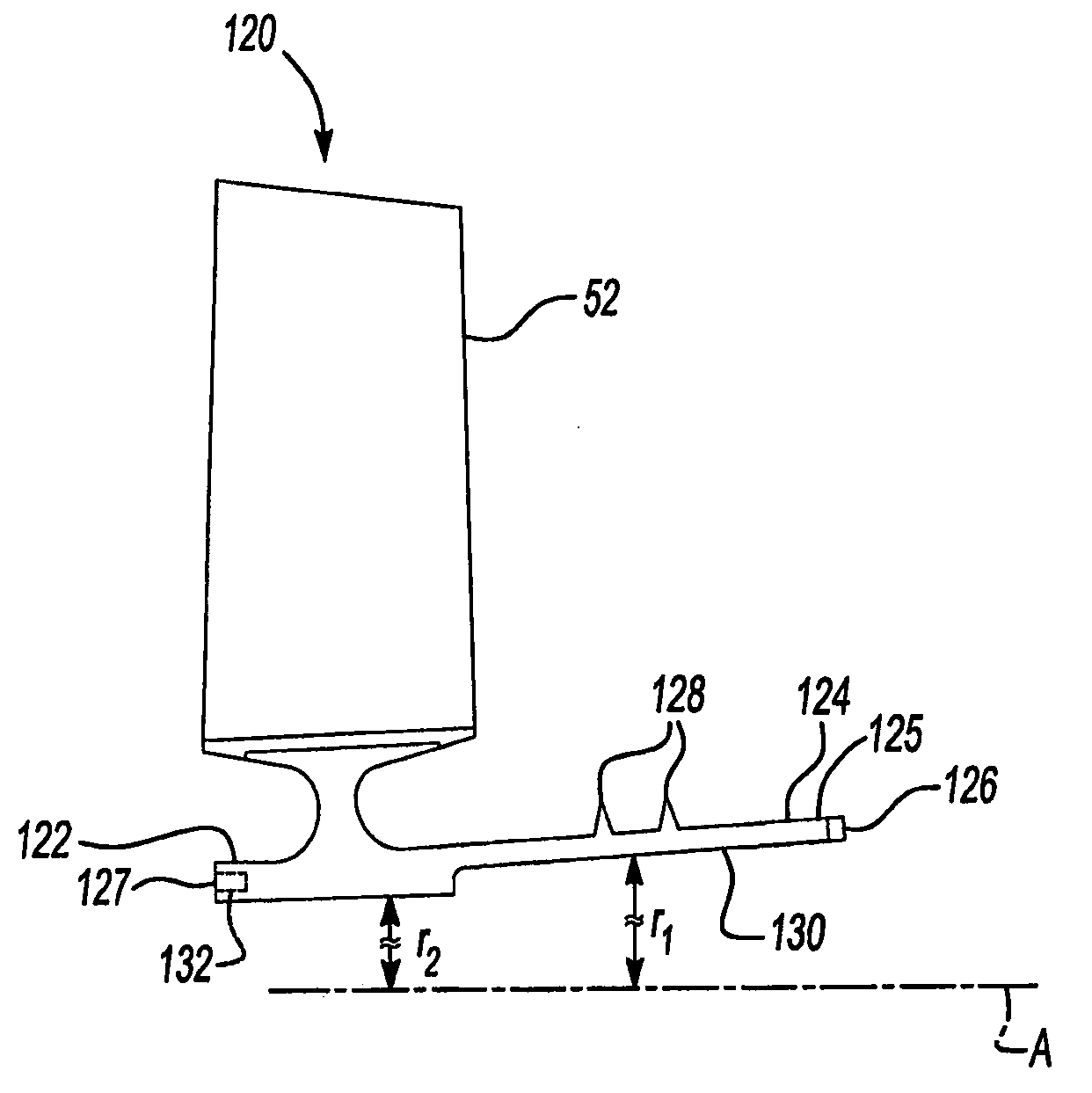
[0008]Each compressor rotor blade assembly is stacked sequentially on a rotor center-tie along the axis of the axial compressor. The spacer portion of each compressor rotor blade assembly abuts the rotor portion of the adjacent compressor rotor blade assembly to retain the adjacent rotor blade assembly on the rotor center-tie. By stacking the compressor rotor blade assemblies sequentially and then retaining them, the typical split cases and the rotor bolts can be (but need not be) eliminated. Eliminating split case flanges and bolts reduces the weight and cost of the turbine engine. Since all the split case flanges can be eliminated, this design also lends itself to counter-rotating axial compressor and / or turbine designs where split cases would have structural difficulties.

Problems solved by technology

The axial flow relationship results in a relatively complicated elongated engine structure of considerable length relative to the engine diameter.
This elongated shape may complicate or prevent packaging of the engine into particular applications.
These conventional root connections increase the overall weight of the axial compressor rotor blade assemblies, as do the conventional connections between the multiple axial compressor rotor blade assemblies themselves.

Method used


Image

  • Stacked annular components for turbine engines
  • Stacked annular components for turbine engines
  • Stacked annular components for turbine engines

Examples


Embodiment Construction

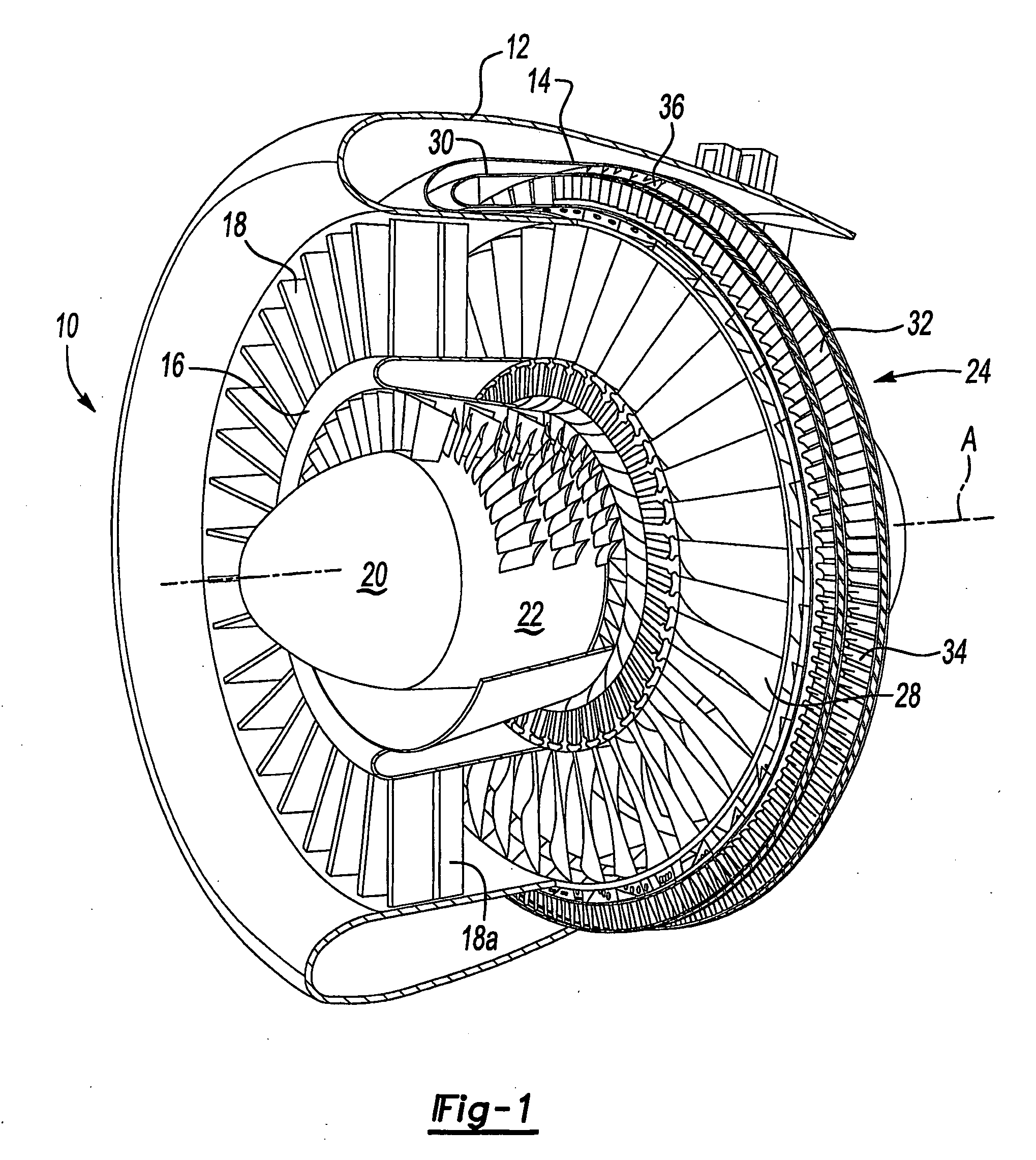
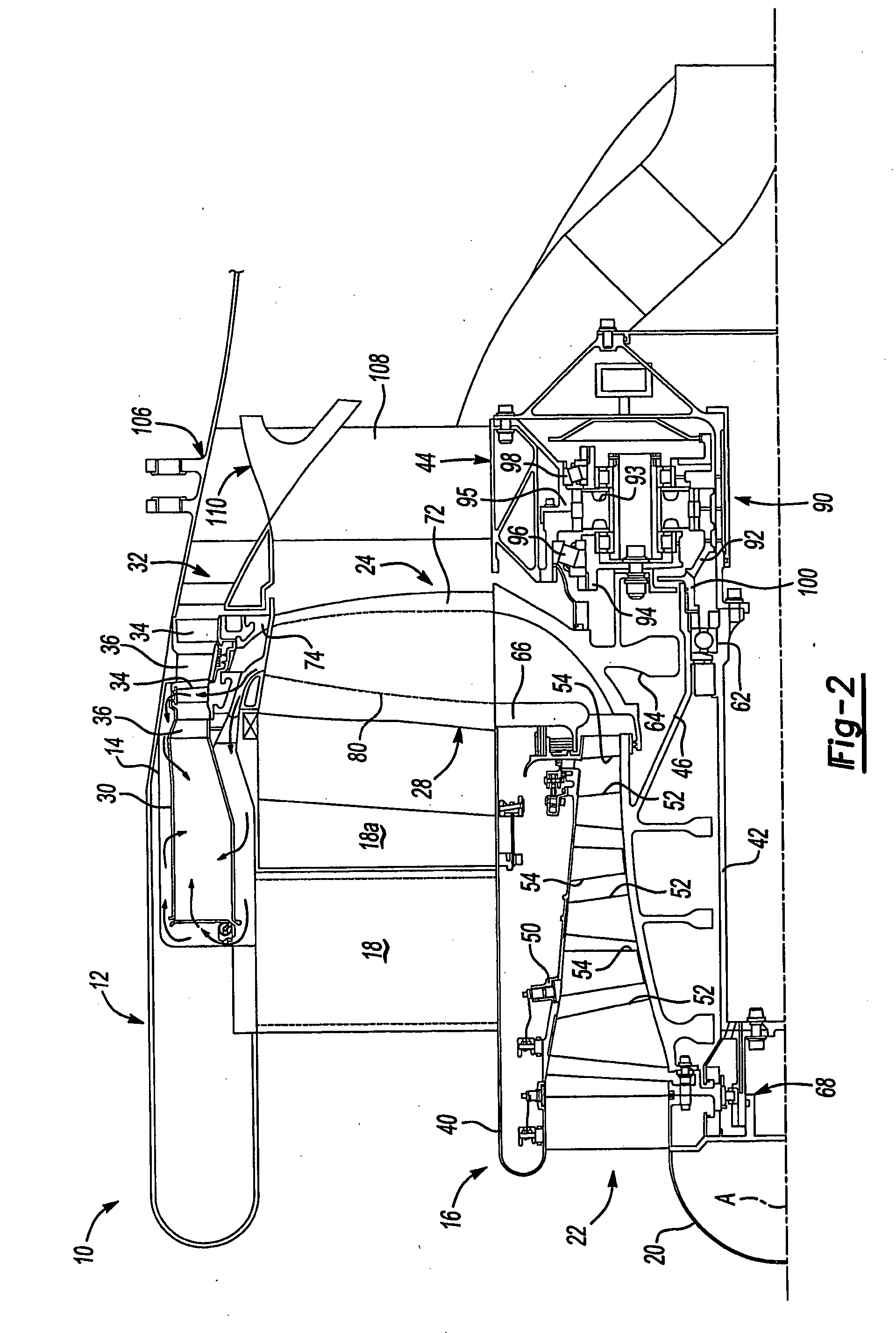
[0016]FIG. 1 illustrates a general perspective partial sectional view of a tip turbine engine (TTE) type gas turbine engine 10. The engine 10 includes an outer nacelle 12, a rotationally fixed static outer support structure 14 and a rotationally fixed static inner support structure 16. A plurality of fan inlet guide vanes 18 are mounted between the static outer support structure 14 and the static inner support structure 16. Each inlet guide vane preferably includes a variable trailing edge 18a.

[0017]A nosecone 20 is preferably located along the engine centerline A to improve airflow into an axial compressor 22, which is mounted about the engine centerline A behind the nosecone 20. A fan-turbine rotor assembly 24 is mounted for rotation about the engine centerline A aft of the axial compressor 22. The fan-turbine rotor assembly 24 includes a plurality of hollow fan blades 28 to provide internal, centrifugal compression of the compressed airflow from the axial compressor 22 for distr...


PUM

PropertyMeasurementUnit
Thicknessaaaaaaaaaa
Pressureaaaaaaaaaa
Diameteraaaaaaaaaa

Abstract

Improved annular components and improved methods for assembling annular components into a turbine engine are described with respect to an axial compressor having a plurality of annular compressor rotor airfoil assemblies (120) as an example. Each compressor rotor airfoil assembly comprises an annular rotor portion (122), a spacer portion (124) extending axially therefrom and a plurality of airfoils (52) extending radially therefrom. The plurality of airfoils may be integrally formed with the annular portion. The compressor rotor airfoil assemblies are stacked sequentially on a center-tie (134) or outer circumferential tie. The spacer portion of one compressor rotor airfoil assembly (120a) abuts the annular rotor portion of the adjacent compressor rotor airfoil assembly (120b) to retain one another on the center-tied outer circumferential tie. By stacking the compressor rotor airfoil assemblies sequentially and then retaining them, the typical split cases, flanges and rotor bolts may be eliminated.

Description

[0001]This invention was conceived in performance of U.S. Air Force contract F33657-03-C-2044. The government may have rights in this invention.BACKGROUND OF THE INVENTION[0002]The present invention relates to turbine engines, and more particularly to improved annular components, such as axial compressor components for a turbine engine, and methods of assembling same in a turbine engine.[0003]An aircraft gas turbine engine of the conventional turbofan type generally includes a forward bypass fan, a low pressure compressor, a high pressure compressor, a combustor, a high pressure turbine, and a low pressure turbine, all located along a common longitudinal axis. The low and high pressure compressors are rotatably driven to compress entering air to a relatively high pressure. This high pressure air is then mixed with fuel in the combustor, where it is ignited to form a high energy gas stream. This gas stream flows axially aft to rotatably drive the high pressure turbine, which rotatabl...

Claims


Application Information

Patent Timeline
IPC IPC(8): F01D5/02F01D5/34B23P15/04
CPCF01D5/025F01D5/34F02C3/067Y10T29/49321F02K3/068Y02T50/671F02C3/073Y02T50/60
Inventor SUCIU, GABRIEL L.ROBERGE, GARY D.MERRY, BRIAN
Owner RAYTHEON TECH CORP
Learn More