
Waterless, low volatile organic compound and carbon dioxide emission, modular paint system and method of performing the same

Inactive Publication Date: 2009-06-18
PLASTECH ENGINEERED PRODUCTS
View PDF1 Cites 0 Cited by
  • Summary
  • Abstract
  • Description
  • Claims
  • Application Information

AI Technical Summary

Benefits of technology

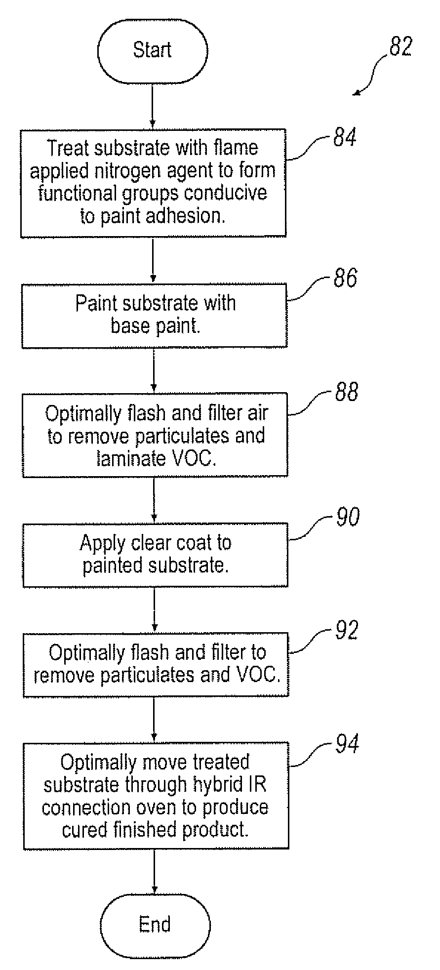
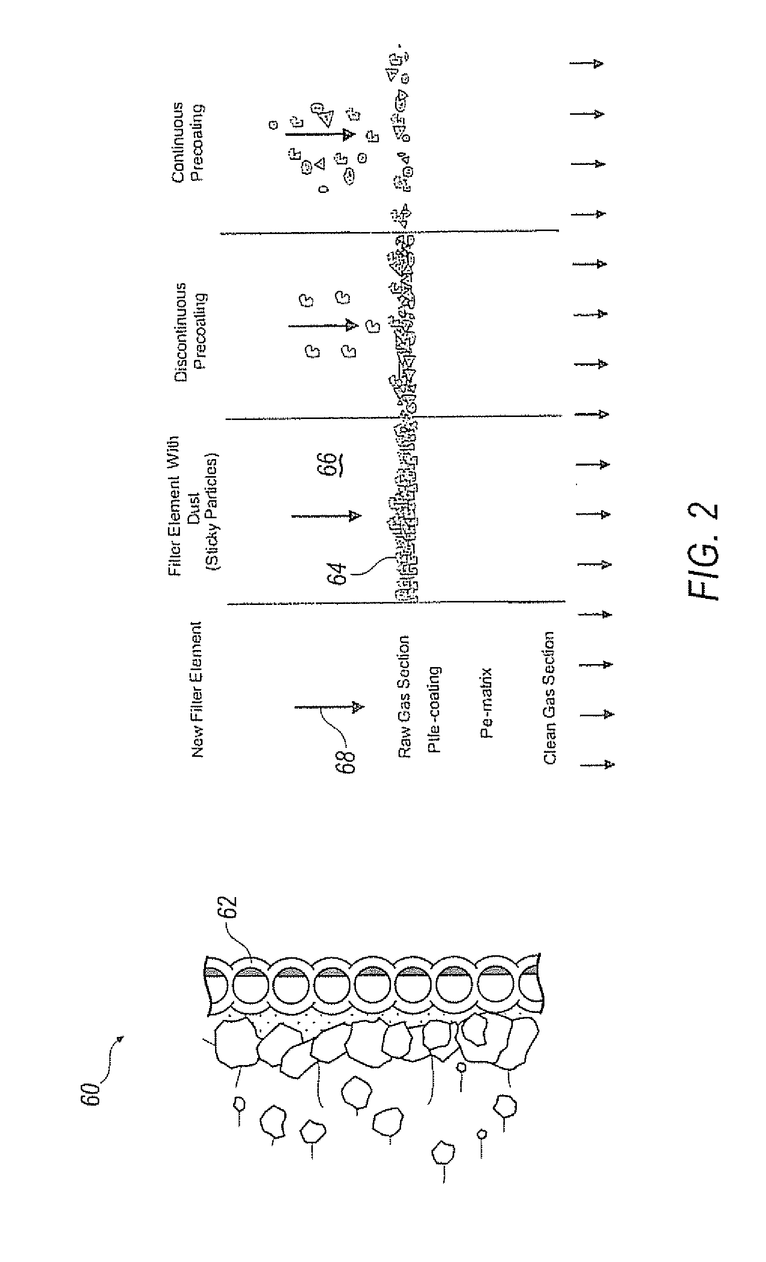
[0007]The system further includes a waterless filtration system for capturing paint over-spray and particulate in close proximity to the paint station. The filtration system is generally coated with a layer of pre-filter dry particulate media to attach and hold dry or wet paint particulate matter. The rigid filtration system preferably has a Teflon coated filtration surface as the first surface on the structural element composition adapted to trap particulate matter of paint and pre-filter media. Each element cartridge in the filtration system is further equipped with a pressure sensor to detect a pressure drop across the filter such that, at a predetermined pressure drop, a pulse of air is forced through the filter from the second surface opposite the first surface to force the captured particulate matter into a receptacle for fluidizing and re-use as pre-filter media Thus, there is no need for water and chemicals to clean parts as a preparation for paint nor water and chemicals required to trap paint over-spray and particulate of the paint application process. In addition there is no requirement for an adhesion promoter to prepare for painting the parts nor is any gas consumed in heating the oven thereby, significantly reducing VOC and CO2 emissions.
[0008]The modular system thus described may be configured to accommodate any number of fascia and exterior components from limited production number to mass production of fascia. In addition, because the system is modular, it may be constructed on site or in close proximity to the automotive manufacturing site and expanded or contracted as the product need dictates. Moreover, because it is on site or in close proximity to the manufacturing site, transportation costs and the investment in racking and packaging are eliminated or minimized.

Problems solved by technology

Production of painted, finished thermoplastic fascia and exterior components in limited production numbers, or for mass production, has posed difficulties for suppliers of those components.
In the past, facilities adapted to produce such articles required a large volume of product to make construction of such facilities cost effective.
In addition, there are environmental concerns regarding CO2 footprints, VOC's, and water contaminated with particulate materials from the paint process that required treatment and / or disposal.

Method used


Image

  • Waterless, low volatile organic compound and carbon dioxide emission, modular paint system and method of performing the same
  • Waterless, low volatile organic compound and carbon dioxide emission, modular paint system and method of performing the same
  • Waterless, low volatile organic compound and carbon dioxide emission, modular paint system and method of performing the same

Examples


Embodiment Construction

)

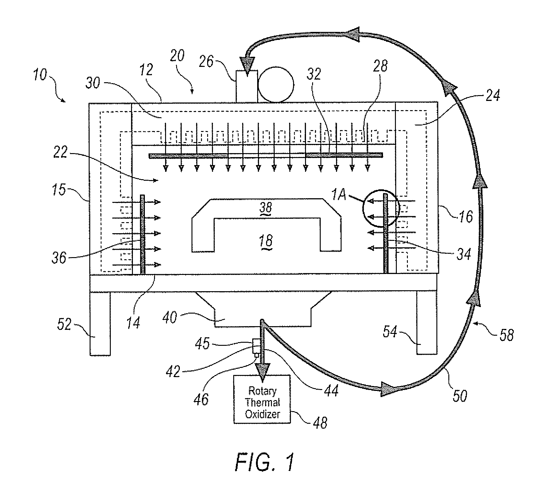
[0013]Turning now to the drawings wherein like numbers refer to like structures, and particularly to FIG. 1, there is depicted an infrared convection paint bake oven 10 is schematically presented in sectional form. Oven 10 has a top 12 and a bottom 14 substantially parallel to each other. The top and bottom are separated by sidewalls 15 and 16 that extend substantially parallel to each other and substantially unbroken therebetween to define a tunnel 18. The bottom has at least two, and preferably a series, of legs 52, 54 arranged periodically along its length. The tunnel has an exterior 20 and an interior 22. The sidewalls and top may be hollow and serve as ducts, or may be equipped with air ducts 24 that are connected to at least one air pressure blower unit 26 at one end and terminate in a series of openings 28 that communicate with the interior of the tunnel such that an air plenum 30 is formed to facilitate the movement of air from the blower through the ducts and passed over i...


PUM


Abstract

The present invention is directed to a modular waterless, low VOC and CO2 emission system to produce thermoplastic resin fascia and exterior components for automotive uses and a method of performing the same. The system and method disclosed have reduced environmental aspects and are adaptable to be used to accommodate any number of products.

Description

BACKGROUND OF THE INVENTION[0001]Production of painted, finished thermoplastic fascia and exterior components in limited production numbers, or for mass production, has posed difficulties for suppliers of those components. In the past, facilities adapted to produce such articles required a large volume of product to make construction of such facilities cost effective. In addition, there are environmental concerns regarding CO2 footprints, VOC's, and water contaminated with particulate materials from the paint process that required treatment and / or disposal. Because large product quantities were required to make production economically feasible, such production facilities tended to be constructed away from individual original equipment manufacturers but in geographical encatchment locations and transported significant distances to the automotive site under just in time manufacturing guidelines.[0002]With the increasingly fractionated automotive market, smaller production runs are bei...

Claims


Application Information

Patent Timeline
IPC IPC(8): B05D3/00B05C11/02
CPCB05B15/1225B05B15/1233B05D3/0254B05D7/53B05D3/08B05D3/101B05D7/02B05D3/0263B05B14/40B05B14/49Y02P70/10
Inventor BROWN, JULIE N.WILLIAMS, GLENN
Owner PLASTECH ENGINEERED PRODUCTS
Learn More