Chemical liquid injection system

Active Publication Date: 2009-06-18
NEMOTO KYORINDO KK
View PDF11 Cites 50 Cited by
  • Summary
  • Abstract
  • Description
  • Claims
  • Application Information

AI Technical Summary

Benefits of technology

[0025]In the chemical liquid injection system, only when the liquid syringe is appropriately held by the cylinder holding mechanism, the data on the RFID tag can be received by the RFID reader. Then, the piston d

Problems solved by technology

However, since some liquid syringes have the same or similar appearances even when they contain different types of liquid, this leads to the possibility that the operator may mount the liquid syringe containing an inappropriate liquid on the chemical liquid injector.
In some cases, an improper product for a chemical liquid injector may be used as a liquid syringe.
In this case, the inappropriate performance thereof such as low resistance to pressure may cause medical malpractice

Method used


Image

  • Chemical liquid injection system
  • Chemical liquid injection system
  • Chemical liquid injection system

Examples


Embodiment Construction

[0067]An embodiment of the present invention will hereinafter be described with reference to the figures. Chemical liquid injection system 1000 of the embodiment according to the present invention comprises chemical liquid injector 100, liquid syringe 200, and CT scanner 300 which serves an imaging diagnostic apparatus. The system is provided for taking diagnostic images of a patient (not shown) injected with a liquid such as a contrast medium, described later in detail.

[0068]As shown in FIGS. 4 and 5, CT scanner 300 includes imaging diagnostic unit 301 and imaging control unit 302. Imaging diagnostic unit 301 and imaging control unit 302 are wire-connected through communication network 303. Imaging diagnostic unit 301 shoots diagnostic images of a patient. Imaging control unit 302 controls the operation of imaging diagnostic unit 301.

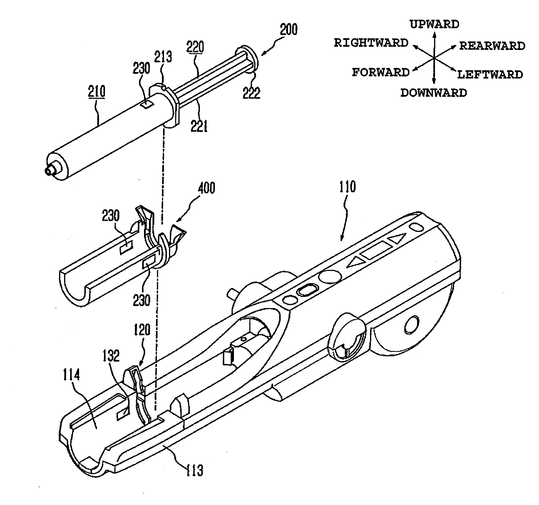
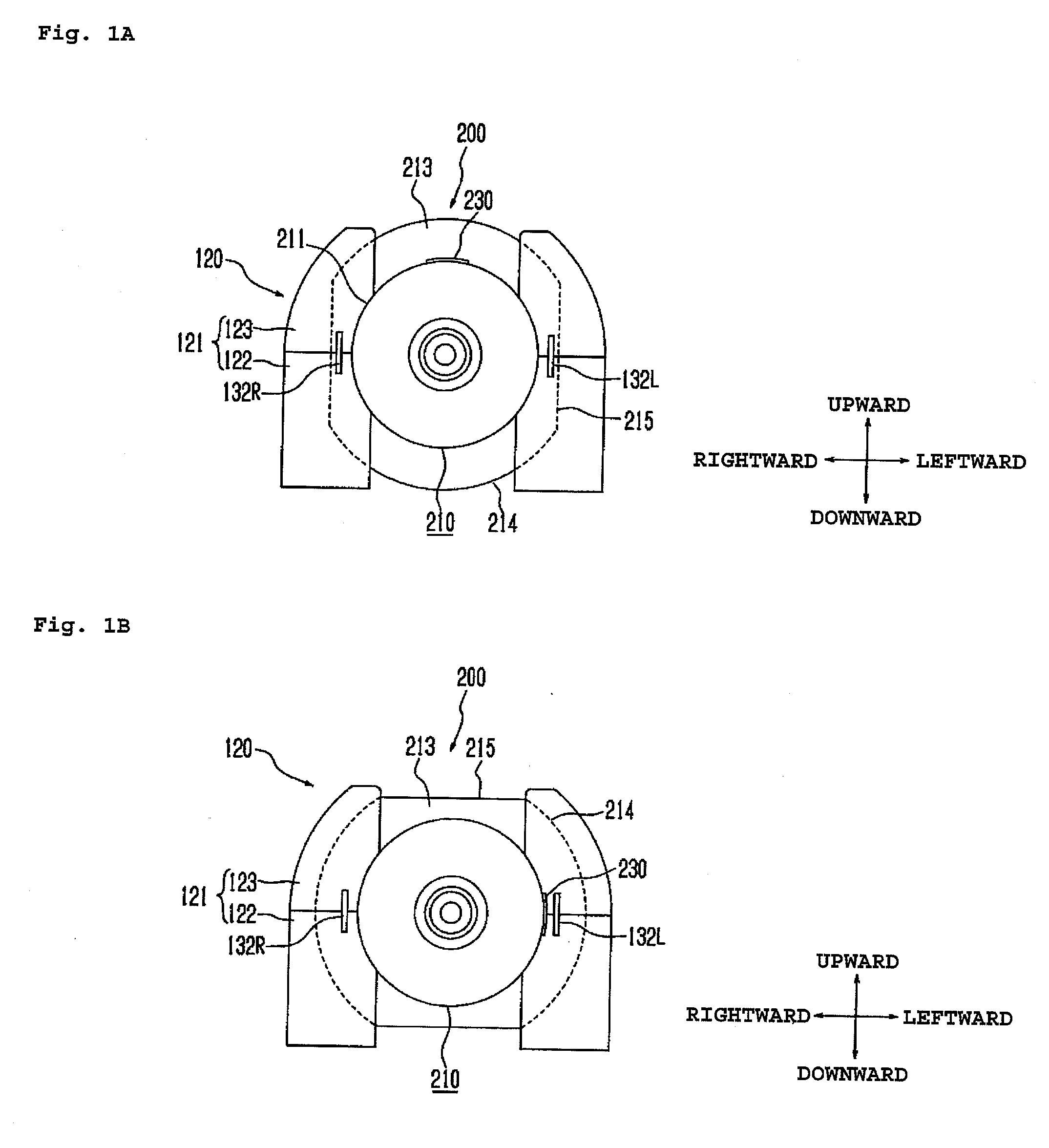
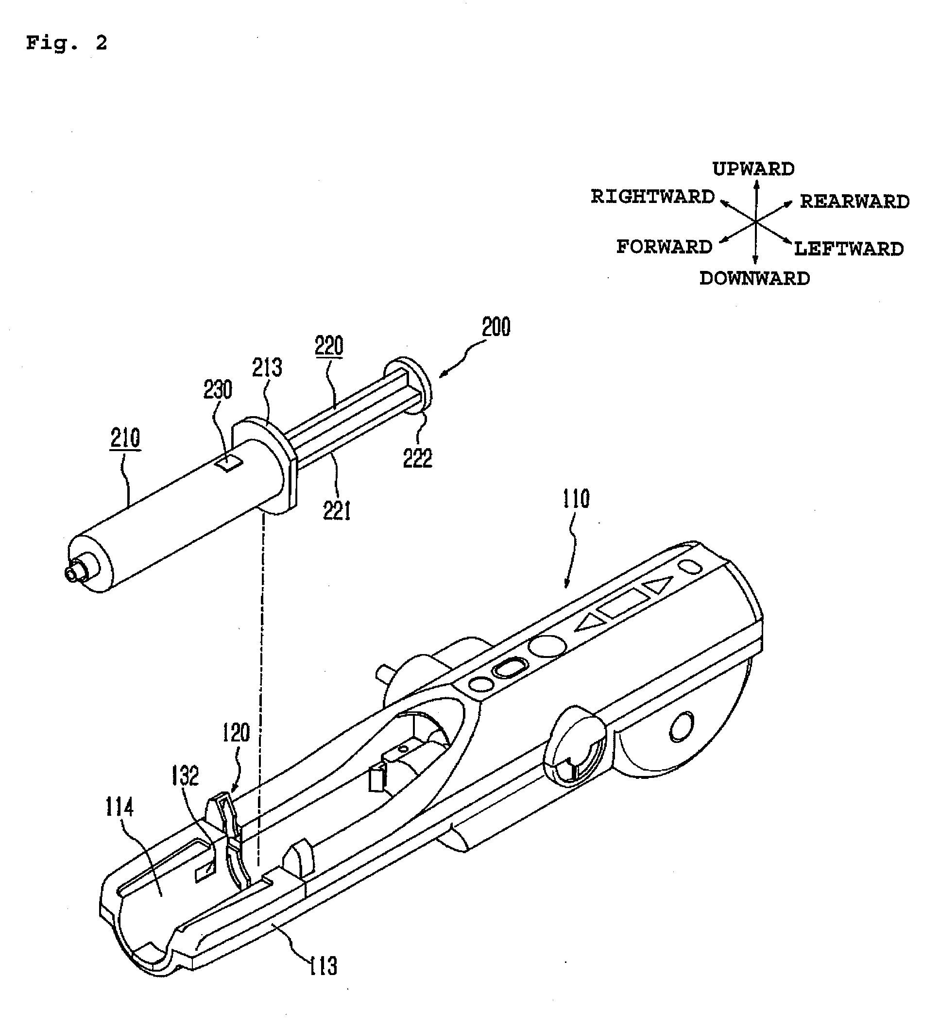
[0069]As shown in FIGS. 2 and 6, liquid syringe 200 comprises cylinder member 210 and piston member 220. Piston member 220 is slidably inserted into c...


PUM


Abstract

A chemical liquid injector comprises liquid syringe 200 and a chemical liquid injector. Liquid syringe 200 has cylinder member 210, a piston member and RFID tag 230 put on an outer circumference of cylinder member 210. The chemical liquid injector has cylinder holding mechanism 120 for holding cylinder member 210, a piston driving mechanism for driving the piston member and an RFID reader. The RFID reader has reader antennas 132L, 132R placed opposite to a tag antenna so as to be able to receive data from RFID tag 230 with cylinder member 210 is appropriately held by the cylinder holding mechanism. The piston driving mechanism is permitted to operate only when the RFID reader receives data from RFID tag 230.

Description

TECHNICAL FIELD[0001]The present invention relates to a chemical liquid injection system for injecting a liquid into a patient from a liquid syringe with a chemical liquid injector, and more particularly, to a chemical liquid injection system for injecting a contrast medium into a patient whose diagnostic images are taken by an imaging diagnostic apparatus such as a CT (Computed Tomography) scanner.BACKGROUND ART[0002]Presently available imaging diagnostic apparatuses for capturing diagnostic images of patients include CT scanners, MRI (Magnetic Resonance Imaging) apparatuses, PET (Positron Emission Tomography) apparatuses, ultrasonic diagnostic apparatuses, CT angiography apparatuses, MRA (MR angiography) apparatuses and the like. When the abovementioned imaging diagnostic apparatuses are used, a liquid such as a contrast medium and physiological saline may be injected into a patient. Chemical liquid injectors for automatically performing the injection have been put into practical ...

Claims


Application Information

Patent Timeline
IPC IPC(8): A61B6/00G06F17/00
CPCA61M5/007A61M5/14546A61M5/1456A61M5/16827A61M5/1785A61B6/4494A61M2205/3317A61M2205/3569A61M2205/3592A61M2205/60A61M2205/6054A61M5/3202
Inventor NEMOTO, SHIGERUSAKAKIBARA, MASAHIRO
Owner NEMOTO KYORINDO KK
Why Eureka
Try Eureka