Sliding Seat And Exhaust Gas Treatment Facility

a technology of exhaust gas treatment facility and sliding seat, which is applied in the field of sliding seat, can solve the problems of comparatively high mechanical load on the pipe or the respective structural support part, conventional sliding seat, cooling system and exhaust gas system, etc., and achieve the effect of reducing the mechanical load within the sliding seat and sufficient sealing

Active Publication Date: 2009-06-25
PUREM GMBH
View PDF22 Cites 25 Cited by
  • Summary
  • Abstract
  • Description
  • Claims
  • Application Information

AI Technical Summary

Benefits of technology

[0008]Embodiments of the invention are based on the general idea to equip the respective sliding seat with a bearing material which, on the one hand, is mounted to the respective structural part with the aid of a coaxially enclosing retaining pipe and which on the other hand, is radially supported on the outside of the pipe. In operation, the pipe is able to slide along the bearing material when its length changes due to a thermal load. Since such a bearing material may have a certain elastic flexibility, the mechanical load of the pipe or the structural part within the sliding seat is reduced. At the same time it is possible to cushion or dampen radially orientated relative movements between pipe and structural part, which may arise due to vibrations when in operation. Associated noises may thereby be effectively reduced. In addition it is possible, in principle, to configure the respective bearing material with a tightness which will ensure sufficient sealing of the sliding seat. With this arrangement the retaining pipe, on the one hand, ensures axial guiding of the pipe thereby increasing the mechanical stability of the sliding seat. On the other hand, the retaining pipe allows bearing material to be used which in axial direction has comparatively large dimensions. This leads to an increase in the sealing effect and a reduction in the load on the bearing material when in operation.

Problems solved by technology

This problem occurs, for example, in heating systems, cooling systems and exhaust gas systems.
This is unfavourable for applications which require a certain gas-tightness because it is, in principle, possible for a gas exchange to take place through the sliding seat.
Furthermore conventional sliding seats, in principle, suffer from the problem of a comparatively high mechanical load on the pipe or the respective structural support part within the sliding seat.
Mechanical loads are connected with wear and may lead to the development of background noise.

Method used


Image

  • Sliding Seat And Exhaust Gas Treatment Facility
  • Sliding Seat And Exhaust Gas Treatment Facility
  • Sliding Seat And Exhaust Gas Treatment Facility

Examples


Embodiment Construction

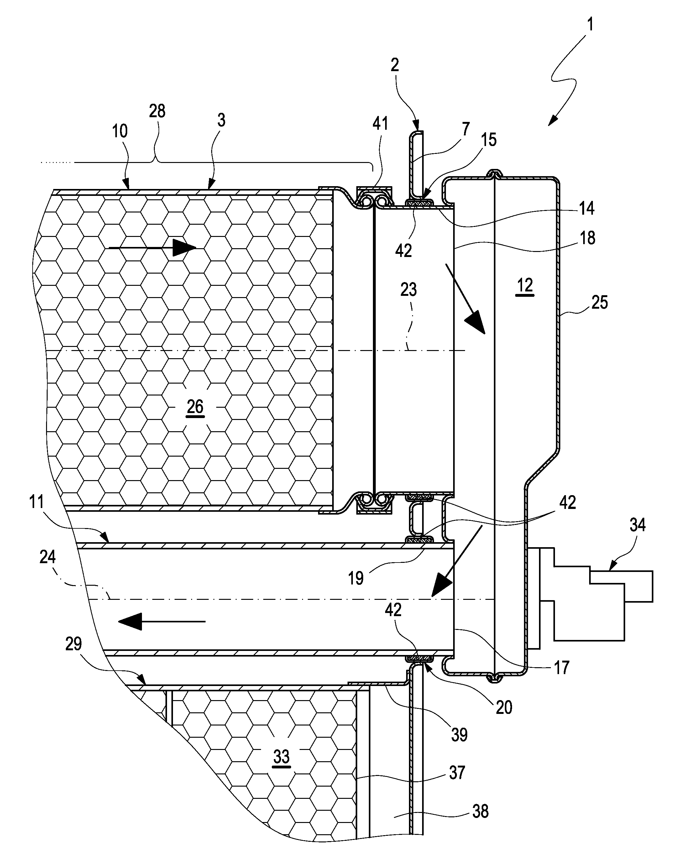
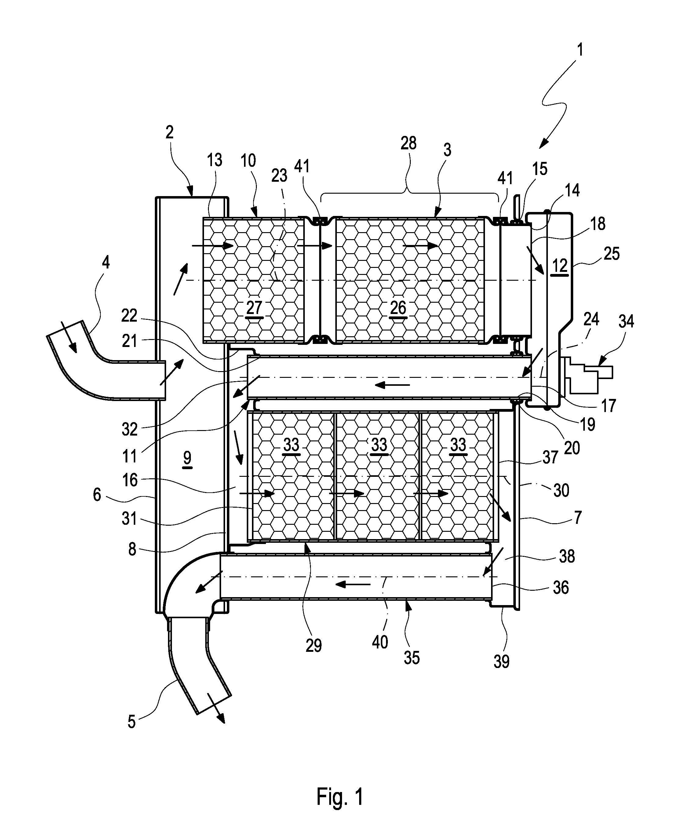
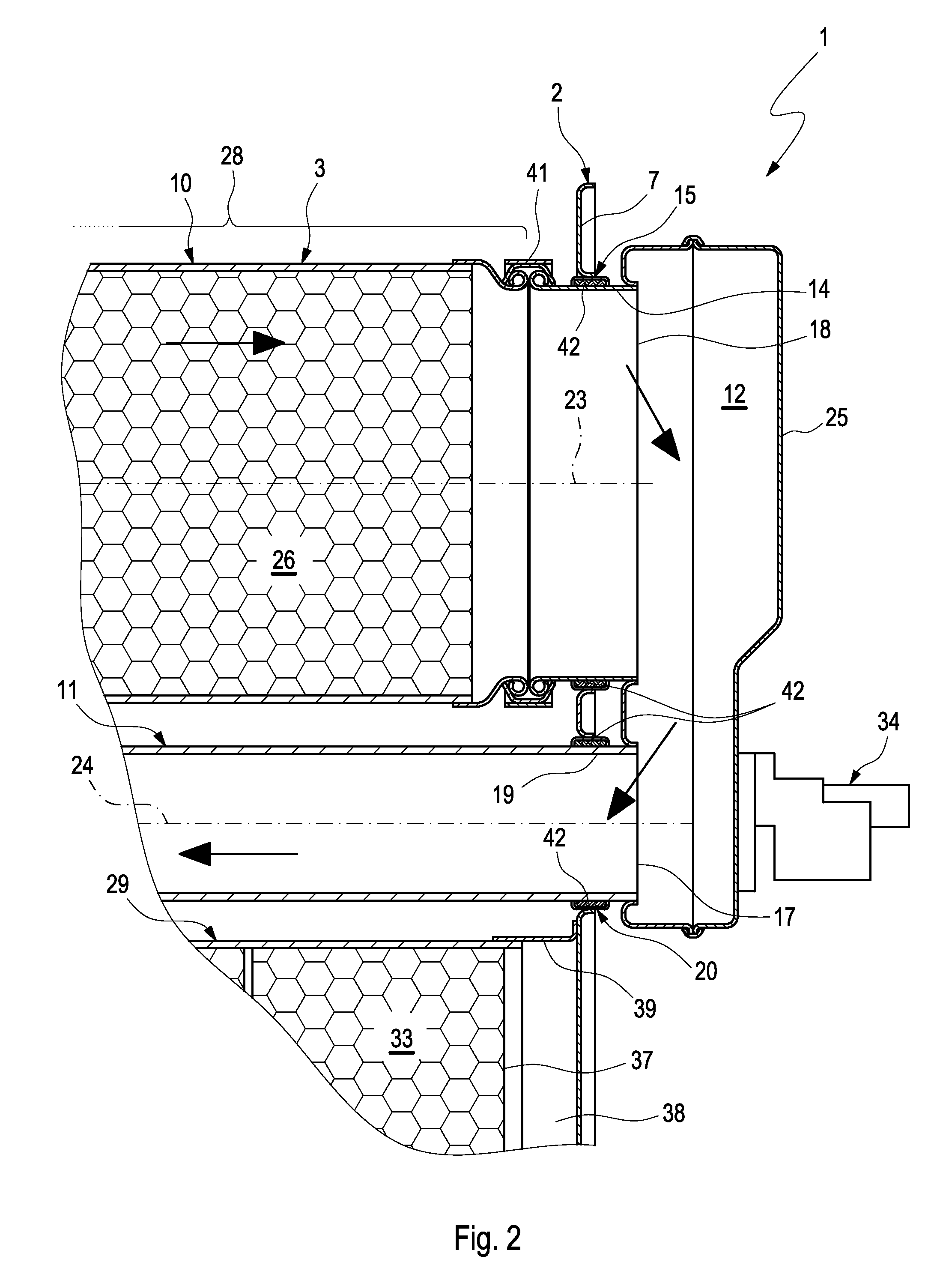
[0019]Referring to FIG. 1, an exhaust gas treatment facility 1 comprises a housing 2 and at least one pipe assembly 3. The housing has at least one inlet 4 and at least one outlet 5. In the embodiment shown the housing 2 has two end floors 6 and 7 as well as an intermediate floor 8. The first end floor 6 and the intermediate floor 8 form the boundaries of an inlet chamber 9. Inlet 4, in the shape of an inlet pipe, is connected to the first end floor 6.

[0020]The pipe assembly 3 comprises at least two pipes communicating with each other, i.e. a first pipe 10 and a second pipe 11. The first pipe 10 communicates with the inlet chamber 9 on the entry side and with a redirecting chamber 12 on the exit side. The first pipe 10 is fastened, in an entry section 13, to a structural support part which is formed here by housing 2 or by a component part of housing 2, in this case by the intermediate floor 8. In an exit section 14, the first pipe 10 with a sliding seat 15 is also fixed on the stru...


PUM


Abstract

The present invention relates to a sliding seat for mounting a thermally impacted pipe on a structural part so as to be axially movable, in particular in an exhaust gas system of a combustion engine, with a bearing material which is radially supported against pipe on the outside thereof and which is fixed on structural part via a retaining pipe fastened on structural part.

Description

CROSS-REFERENCE TO RELATED PATENT APPLICATIONS[0001]This patent application claims the benefit of co-pending German Patent Application No. DE 102007062662.4, filed Dec. 24, 2007, the entire teachings and disclosure of which are incorporated herein by reference thereto.FIELD OF THE INVENTION[0002]The present invention relates to a sliding seat for mounting a thermally impacted pipe on a structural part so as to be axially movable, in particular in an exhaust system of a combustion engine. The invention also relates to an exhaust gas treatment facility with such a sliding seat.BACKGROUND OF THE INVENTION[0003]In order to be able to permanently fasten thermally impacted pipes on a support, it is common to mount the respective pipe on the support using a fixed bearing on the one hand, and a movable bearing on the other, thereby allowing the length of the pipe to change relative to the support without inadmissibly high stresses occurring between pipe and support. Movable bearings of this...

Claims


Application Information

Patent Timeline
Patent Type & Authority Applications(United States)
IPC IPC(8): F01N3/035F01N3/021F01N13/08
CPCF01N1/084F01N13/0097F01N3/2066F01N3/2853F01N13/16F01N13/1811F01N2240/20F01N2310/02F01N2310/04F01N2310/14F01N2470/00F01N2470/22F01N2610/00Y02T10/24F01N3/0222Y02T10/12
Inventor KRAUSE, MICHAELWIELAND, ARTHURWIRTH, GEORGJAMBROSIC, KRESIMIR
Owner PUREM GMBH
Why Eureka
Try Eureka