Vehicle Controller, Vehicle and Vehicle Control Method

a technology for vehicle controllers and controllers, applied in the direction of electric energy management, electric devices, conversion with intermediate conversion to dc, etc., can solve the problems of excessive electrical power, disclose any control of boosting converters, etc., and achieve control failures, sufficient margins, and prevent excessive voltage at inverters

Active Publication Date: 2009-06-25
DENSO CORP
View PDF12 Cites 31 Cited by
  • Summary
  • Abstract
  • Description
  • Claims
  • Application Information

AI Technical Summary

Benefits of technology

[0029]According to the present invention, control failure can be prevented in an emergency in which the rotation speed varies over a wide range at the time of a slip and the like, by switching from the rectangular wave control of lower control response to non-rectangular wave control of higher response and, in addition, excessive voltage at the inverter can be prevented with sufficient margin.
[0030]When a multi-speed transmission is provided, the range of energy fluctuation at the gripping after a slip differs from one speed to another. Therefore, by setting the control mode and the target voltage corresponding to the gearshift, it becomes possible to minimize the range of variation of the target voltage and to prevent excessive voltage at the inverter.

Problems solved by technology

In such a configuration including a boosting converter, when the rotation speed of the motor decreases abruptly, excessive electrical power would be supplied from the boosting converter to the inverter.
Japanese Patent Laying-Open No. 2001-295676 does not disclose any control of the boosting converter at the transition from the slipping state to the gripped state.

Method used


Image

  • Vehicle Controller, Vehicle and Vehicle Control Method
  • Vehicle Controller, Vehicle and Vehicle Control Method
  • Vehicle Controller, Vehicle and Vehicle Control Method

Examples


embodiment 1

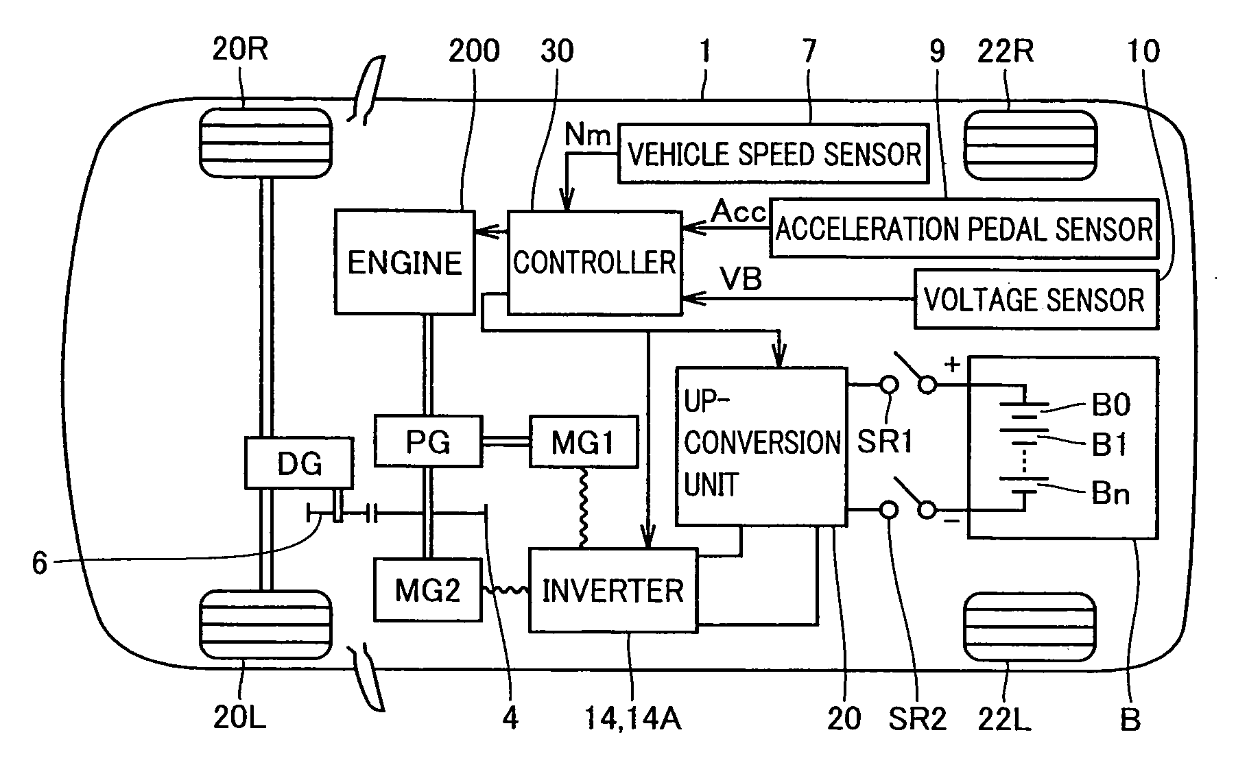
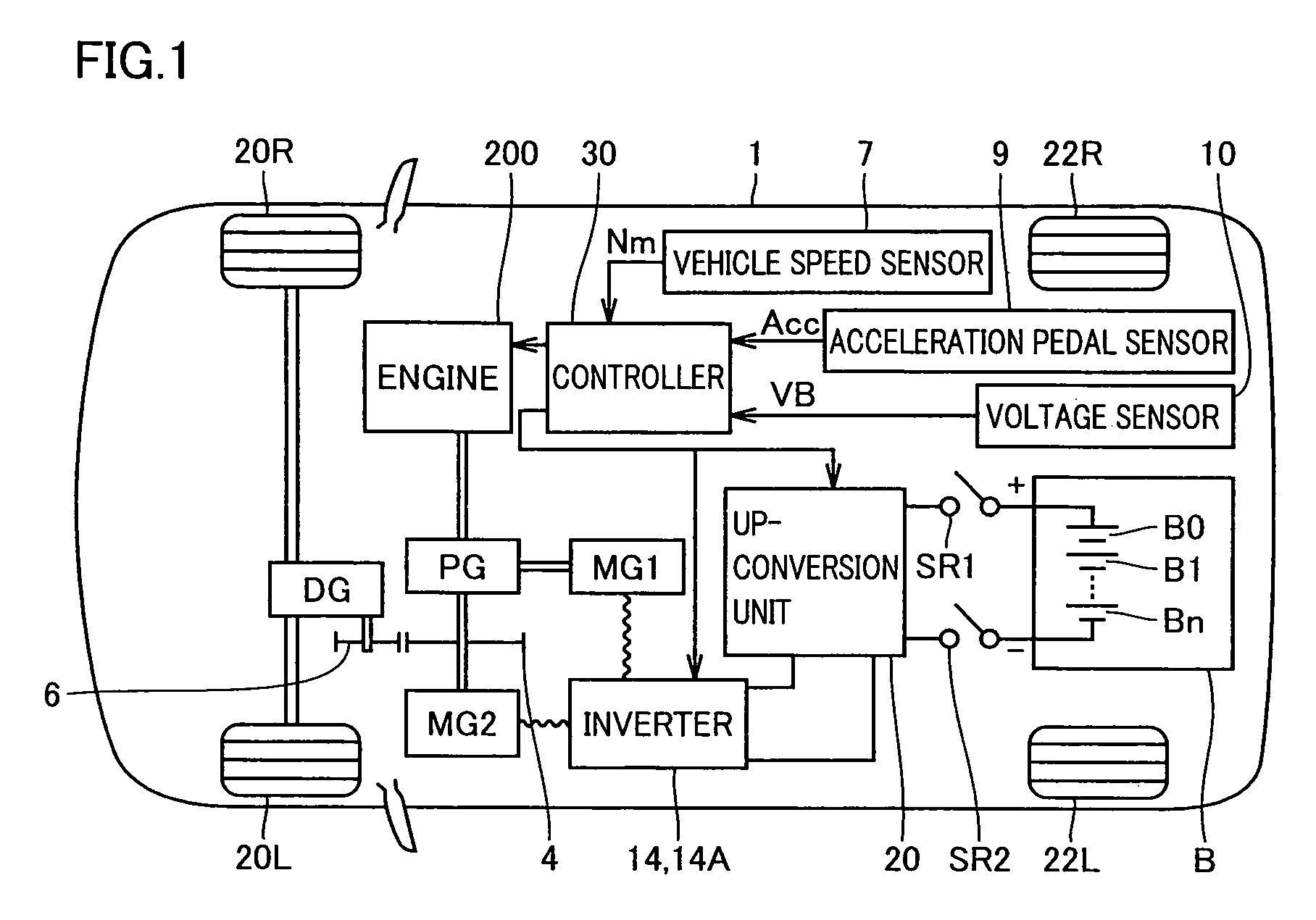
[0052]FIG. 1 schematically shows a configuration of a hybrid vehicle 1 in an embodiment of the present invention.

[0053]With reference to FIG. 1, hybrid vehicle 1 includes front wheels 20R and 20L, rear wheels 22R and 22L, an engine 200, a planetary gear PG, a differential gear DG, and gears 4 and 6.

[0054]Hybrid vehicle 1 further includes a battery B, an up-conversion unit 20 up-converting voltage in a direct current (dc) power output from battery B, and inverters 14, 14A communicating the dc power with up-conversion unit 20.

[0055]Hybrid vehicle 1 further includes a motor generator MG1 receiving power of engine 200 via planetary gear PG to generate electrical power, and a motor generator MG2 having a rotation shaft connected to planetary gear PG. Inverters 14, 14A are connected to motor generators MG1 and MG2 to provide conversion between alternate current (ac) power and dc power provided from the up-conversion circuit.

[0056]Planetary gear PG includes a sun gear, a ring gear, a pinio...

embodiment 2

[0144]In the hybrid vehicle shown in FIG. 1, motor generators MG1 and MG2 and engine 200 have their torque controlled, and are coupled by planetary gear PG as a power distribution mechanism, to realize continuously variable transmission.

[0145]In order to realize both smaller size of the motor generator and required acceleration at high speed running, however, insertion of a transmission at a portion of propeller shaft transmitting power from the planetary gear to a differential gear DG to enable change in gear ratio has been proposed.

[0146]FIG. 10 shows a configuration of a hybrid vehicle 300 on which a transmission allowing two-stage switching of gear ratio is mounted.

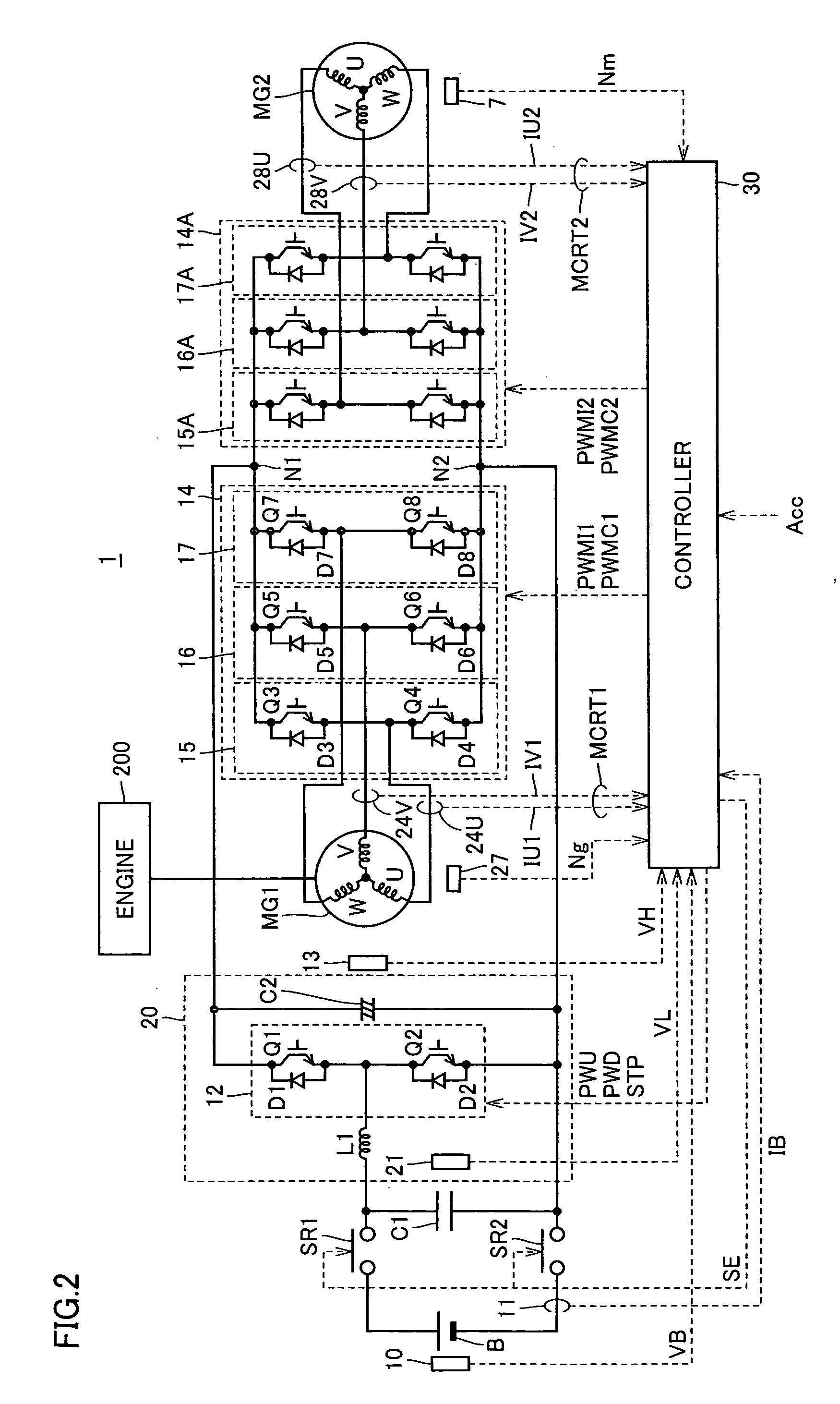
[0147]Referring to FIG. 10, vehicle 300 includes engine 200, motor generator MG1, planetary gear PG, motor generator MG2, and a transmission 307. Up-conversion unit 20 and inverters 14 and 14A of vehicle 400 have the same configuration as those of hybrid vehicle 1 shown in FIG. 2 and, therefore, description thereof wi...


PUM


Abstract

A controller for a vehicle including at least one motor driving wheels, an inverter driving the motor, and a boosting converter supplying a dc power supply current to the inverter, is provided with a control portion performing rectangular wave control and non-rectangular wave control on the inverter in a switched manner. The control portion has an emergency switching condition for switching control from the rectangular wave control to the non-rectangular wave control, as a determination reference, and when the emergency switching condition is satisfied while the rectangular wave control is being executed (YES at step S5), the control portion instructs the boosting converter to lower target output voltage (S7). Preferably, the control portion determines that the emergency switching condition is satisfied when a q-axis current supplied from the inverter to the motor exceeds a prescribed threshold value.

Description

TECHNICAL FIELD[0001]The present invention relates to a vehicle controller and a vehicle and, more specifically, to a controller of a vehicle provided with a vehicle propulsion motor, the vehicle and a method of controlling the vehicle.BACKGROUND ART[0002]Recently, electric vehicles, hybrid vehicles and fuel-cell vehicles have attracting attention as environmentally friendly vehicles. Some hybrid vehicles have already been commercialized.[0003]A hybrid vehicle has, in addition to a conventional engine, a dc power source, an inverter and a motor driven by the inverter as power sources. Specifically, power is obtained by driving the engine and, in addition, dc voltage from the dc power source is converted to ac voltage by the inverter, and the motor is rotated by the converted ac voltage, whereby power is obtained. An electric vehicle has a dc power source, an inverter and a motor driven by the inverter as power sources.[0004]Japanese Patent Laying-Open No. 2001-295676 discloses torqu...

Claims


Application Information

Patent Timeline
Patent Type & Authority Applications(United States)
IPC IPC(8): B60W20/00G06F17/00B60L50/15B60L50/16H02M3/22
CPCB60K6/365B60L3/10B60K6/547B60L11/123B60L11/14B60L15/025B60L2210/14B60W10/08B60W20/00B60W2520/26H02P2201/09Y02T10/6217Y02T10/643Y02T10/7077Y02T10/7225Y02T10/6239B60K6/445B60L2240/527B60L50/61B60L50/16Y02T10/62Y02T10/64Y02T10/72Y02T10/7072Y02T10/70B60W20/15
Inventor HANADA, HIDETOYOKOYAMA, SOJIRO
Owner DENSO CORP
Why Eureka
Try Eureka