Compressor Profile for Resonance Points System and Method

a compressor and resonance point technology, applied in the field of gas compressors, can solve the problems of excessive vibration and movement of the compressor, and affecting the performance of the system, so as to reduce the vibration or movement of the compressor

Inactive Publication Date: 2009-06-25
ILLINOIS TOOL WORKS INC
View PDF31 Cites 23 Cited by
  • Summary
  • Abstract
  • Description
  • Claims
  • Application Information

AI Technical Summary

Benefits of technology

[0006]A method is provided that includes adjusting a compressor to redu

Problems solved by technology

The power output and flow of the gas can affect the performance of the system.
Unfortunately, the compressor may have one or more resonance points, which can cause

Method used


Image

  • Compressor Profile for Resonance Points System and Method
  • Compressor Profile for Resonance Points System and Method
  • Compressor Profile for Resonance Points System and Method

Examples


Embodiment Construction

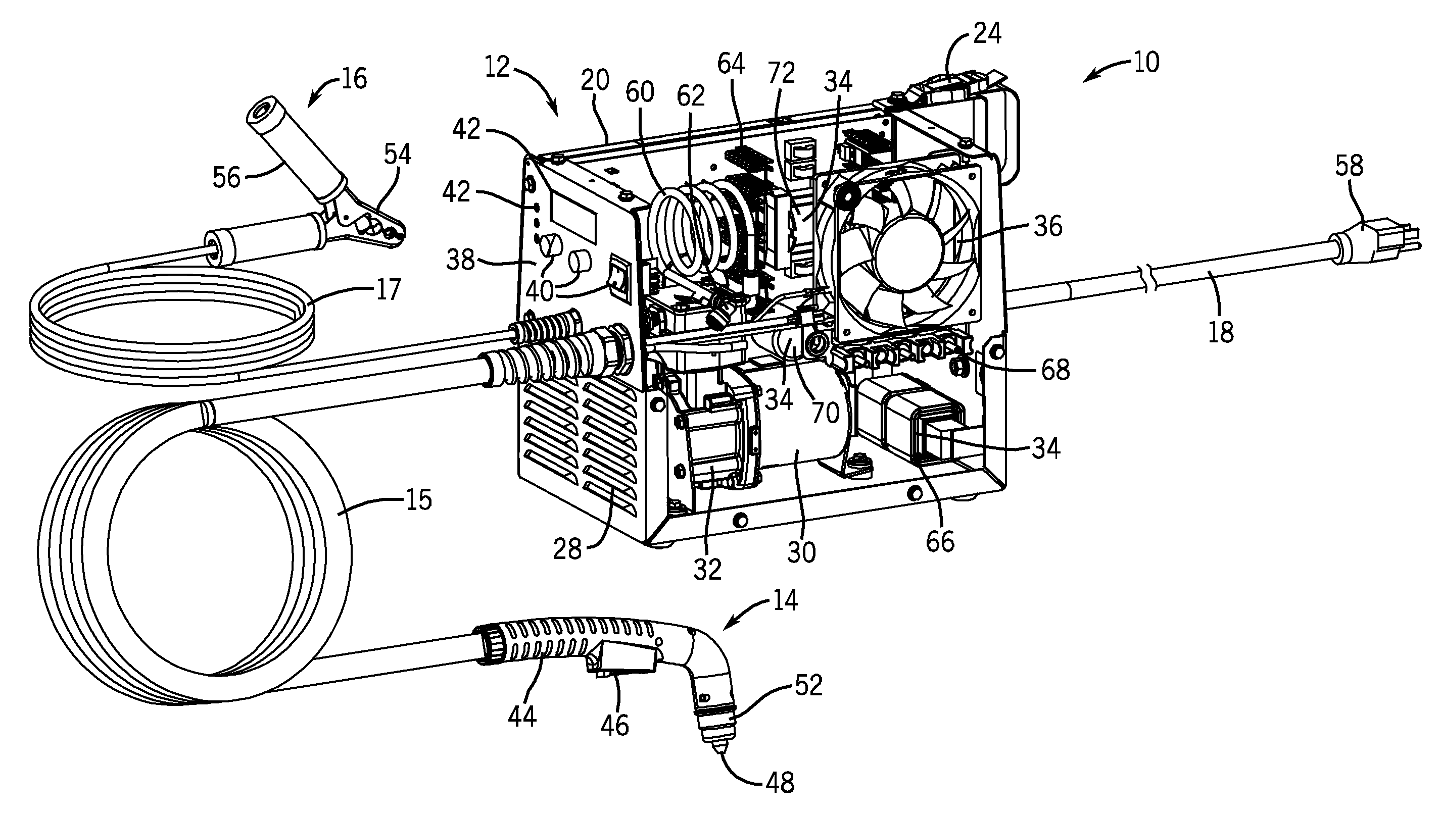
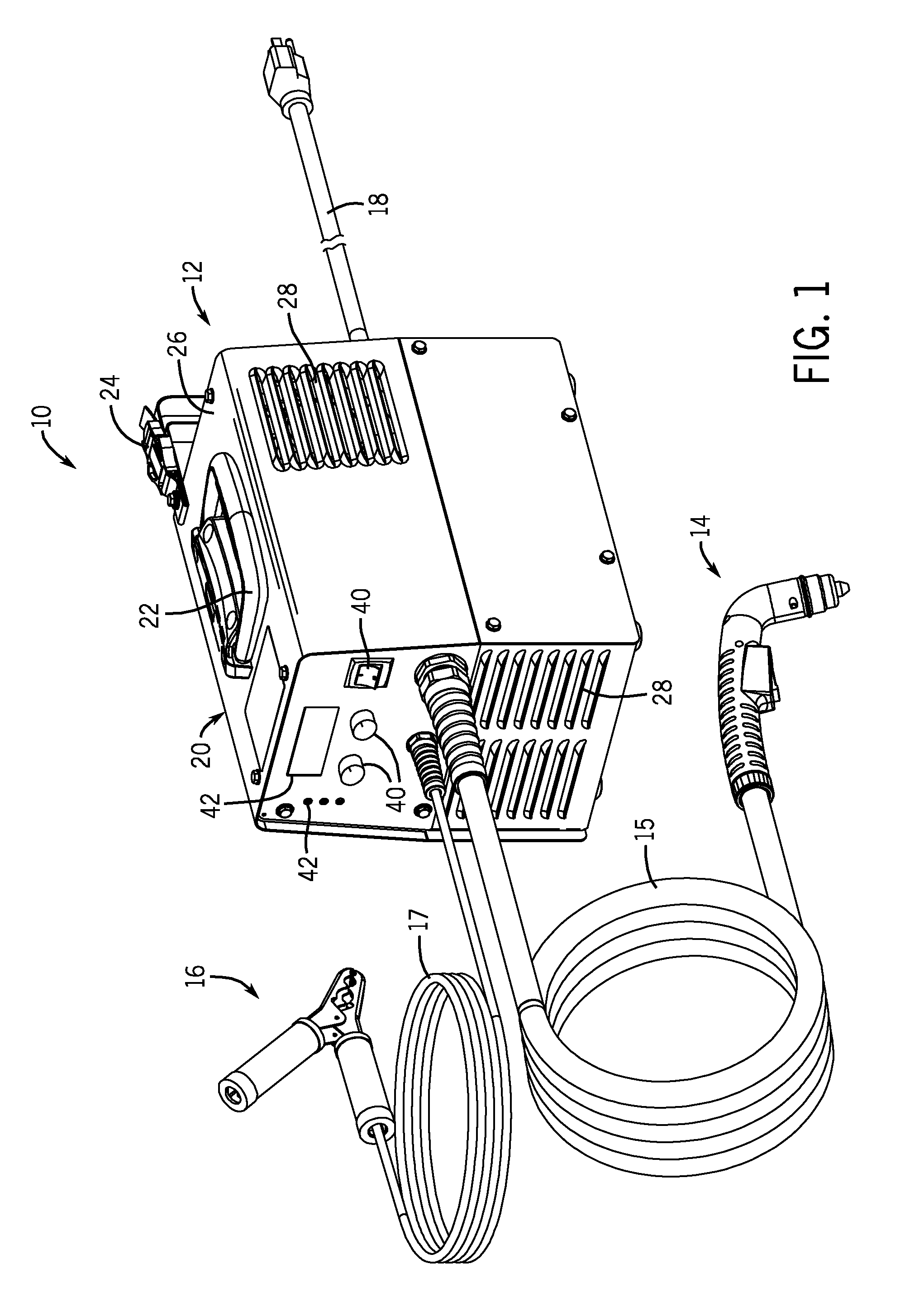
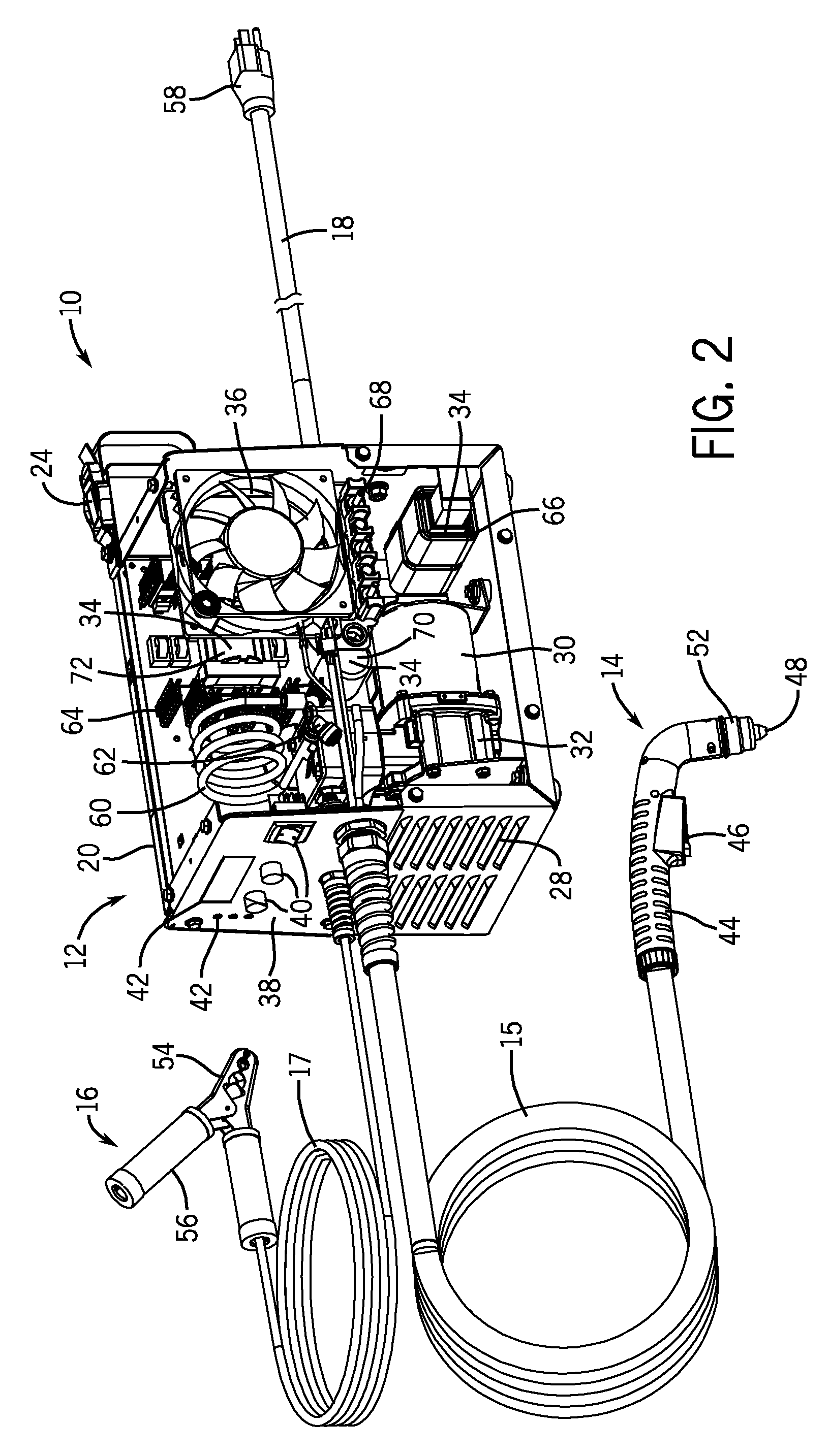
[0015]Referring now to the drawings, FIGS. 1 and 2 are partial perspective views illustrating an embodiment of a portable plasma cutting system 10. Specifically, FIG. 1 illustrates the system 10 with access panels completely assembled to close internal components, whereas FIG. 2 illustrates an entire side panel assembly removed to provide a better view of the internal features and components of the system 10. As discussed in further detail below, embodiments of the system 10 include a compressor controller and one or more profiles configured to start-up and shutdown a compressor by accelerating through one or more resonance points. In this manner, the disclosed controller and profiles may substantially reduce adverse vibrations, movement, wear, and potential damage associated with such resonance points.

[0016]The illustrated plasma cutting system 10 includes a torch power unit 12 coupled to a plasma torch 14 and a work piece clamp 16 via a torch cable 15 and a work piece cable 17, re...


PUM

PropertyMeasurementUnit
Frequencyaaaaaaaaaa
Poweraaaaaaaaaa
Speedaaaaaaaaaa

Abstract

A system is provided that includes a torch power unit. The torch power unit includes a compressor and a controller configured to adjust the compressor based on a profile indicating a resonance point for the compressor. A method is also provided that includes adjusting the compressor to reduce vibrations or movement of the compressor based on a resonance point. A machine-readable medium that includes code that includes instructions to adjust a rate of velocity change based on a resonance point is also provided. A method of operation is provided that includes reducing vibrations associated with a resonance point of the device by increasing the rate of velocity change at the resonance point as compared to non-resonance regions.

Description

CROSS REFERENCE TO RELATED APPLICATIONS[0001]This application claims priority to and the benefit of U.S. Provisional Application No. 61 / 015,163, entitled “Compressor Profile for Resonance Points System and Method,” filed Dec. 19, 2007, the disclosure of which is incorporated herein by reference.BACKGROUND[0002]The invention relates generally to gas compressors, and more particularly to plasma cutting systems utilizing an air compressor in a single unit.[0003]A variety of systems use compressed gas (e.g., compressed air). For example, compressed air may be used to power tools, such as wrenches, sanders, spray guns, and so forth. By further example, compressed gas (e.g. air) may be used with various torches. A plasma cutting system creates plasma (e.g., high temperature ionized gas) to cut metal or other electrically conductive material. In general, an electrical arc converts a gas (e.g., compressed air) into plasma, which is sufficiently hot to melt the work piece while the pressure ...

Claims


Application Information

Patent Timeline
IPC IPC(8): B23K9/10F04B49/00
CPCB23K9/32F04B39/0027F04B35/04B23K10/00
Inventor SOMMERFELD, TROY A.
Owner ILLINOIS TOOL WORKS INC
Why Eureka
Try Eureka