
Tray energy absorber and bumper system

a technology of energy absorption and bumper, which is applied in the direction of bumpers, vehicle components, pedestrian/occupant safety arrangements, etc., can solve the problems of difficult and expensive manufacturing, and achieve the effects of high energy absorption efficiency, fast loading of impact force, and sufficient flexibility

Active Publication Date: 2009-06-25
SABIC GLOBAL TECH BV
View PDF22 Cites 58 Cited by
  • Summary
  • Abstract
  • Description
  • Claims
  • Application Information

AI Technical Summary

Benefits of technology

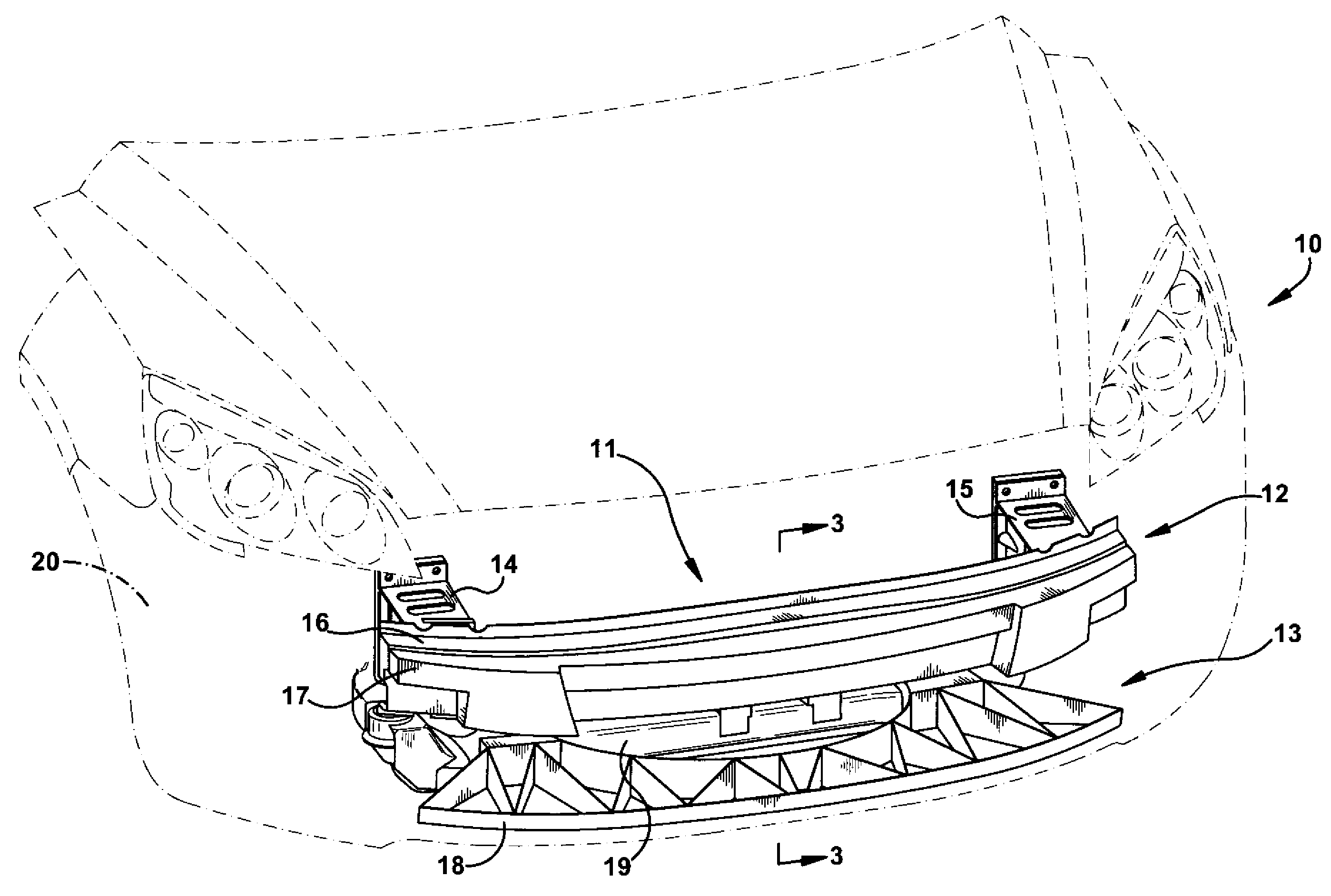
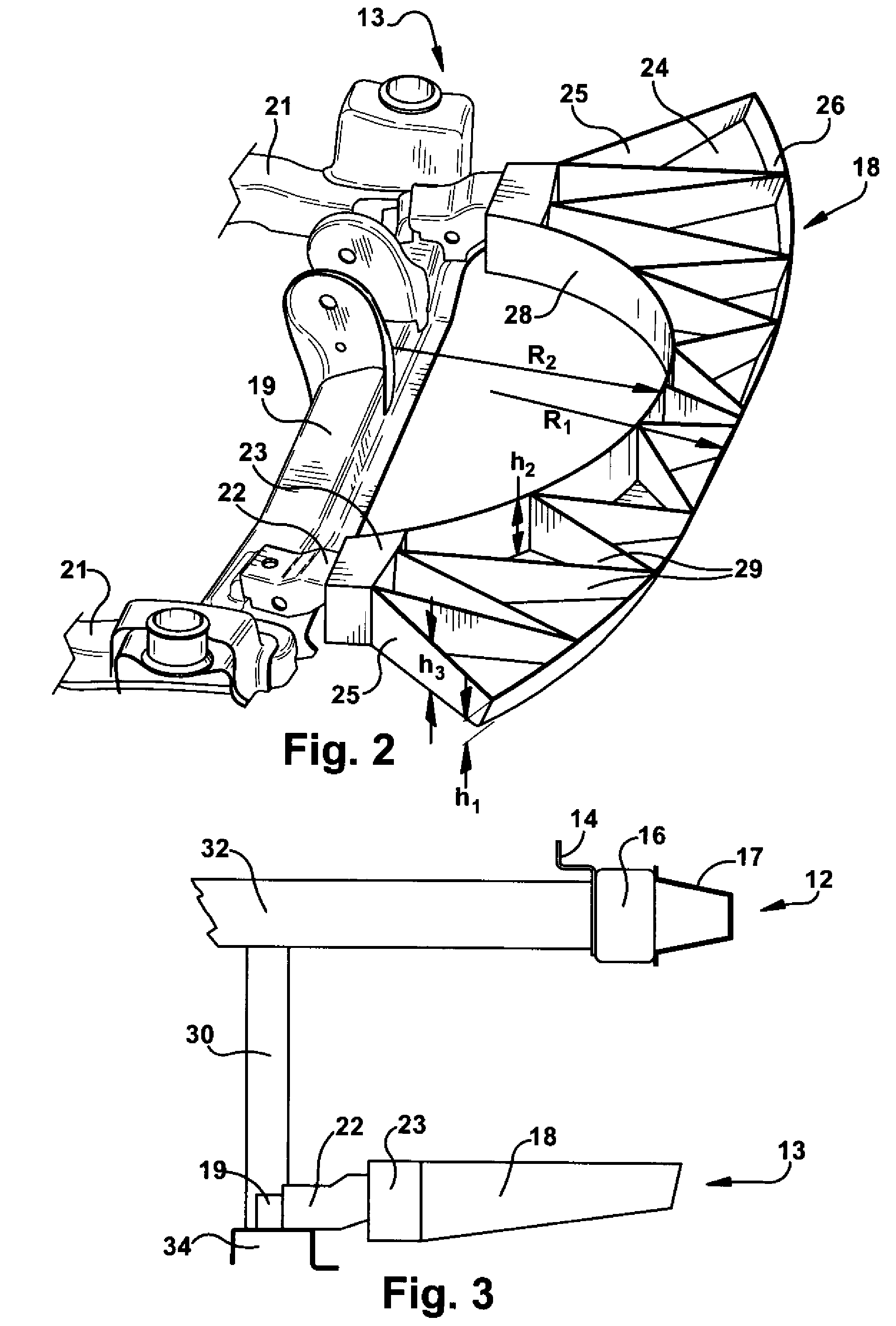
[0005]The present invention provides for various embodiments of a unitary tray energy absorber for attachment to a vehicle. The invention also provides for various bumper systems that include tray energy absorbers. The tray energy absorbers herein have high energy absorption efficiency through fast loading of an impact force, yet are also sufficiently flexible to meet pedestrian safety requirements. The tray energy absorbers can be mounted to a lower bumper to mitigate pedestrian injury at low levels of speed, and particularly, to mitigate lower and upper leg injuries. In one embodiment of the present invention, the tray energy absorber includes a tray comprising a base, a first transverse wall that is arcuate and a second transverse wall extending upward from the base of the tray. The tray energy absorber also includes a plurality of ribs which extend upward from the base of the tray and which connect the first transverse wall to the second transverse wall.
[0009]The bumper system is desirable for applications where low levels of energy need to be absorbed, such as in the area of pedestrian protection upon impact of the front end of an automotive vehicle. Enhanced bumper impact performance translates to reduced costs of repair for low speedfender benders” and greater occupant safety during higher speed collisions.

Problems solved by technology

However, conventional bumper systems and energy absorbers are often too stiff to mitigate pedestrian injury, and / or are otherwise, highly complex having a large number of parts which can make them difficult and expensive to manufacture.

Method used


Image

  • Tray energy absorber and bumper system
  • Tray energy absorber and bumper system
  • Tray energy absorber and bumper system

Examples


Embodiment Construction

[0026]The present invention provides for a tray energy absorber that can be used in automotive vehicles, for example, as a component of a multi-part vehicle bumper system. The unitary tray energy absorber functions to quickly absorb impact energy while meeting pedestrian safety requirements to mitigate pedestrian leg injuries at low levels of speed. The tray energy absorber can also function as a “spoiler” to prevent formation of wakes, or low pressure zones, under the hood area of the vehicle and / or prevent foreign particles from entering the area. The tray energy absorber can be formed as a one-piece component to facilitate easier manufacturing and assembly when used in a bumper system, for example. The design and rigidity of the tray energy absorber can vary according the design of the vehicle.

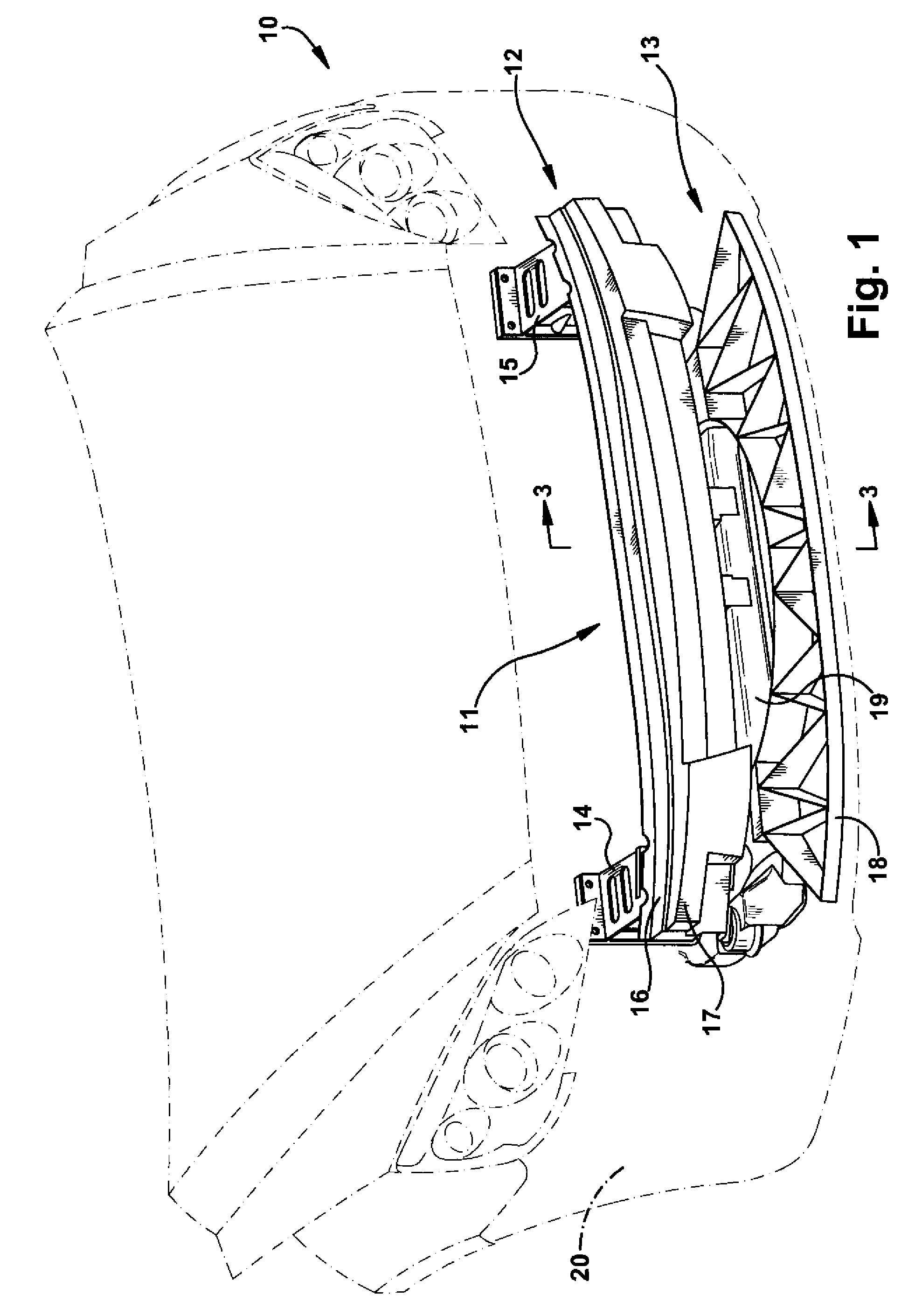
[0027]FIG. 1 is a schematic diagram of the front portion of a vehicle 10 which shows bumper system 11 which includes an upper bumper portion 12 and a lower bumper portion 13, according to a...


PUM


Abstract

The present invention provides for various embodiments of a tray energy absorber comprising a base, a first transverse wall that is arcuate and extends from the base, a second transverse wall spaced apart from the first transverse wall and which extends from the base. The tray energy absorber further comprises a plurality of ribs that extend from the base joining the first transverse wall to the second transverse wall. In one embodiment the density of the ribs varies along the transverse width of the tray energy absorber. In another embodiment at least one of the plurality of ribs is greater than 50% of the height of the first transverse wall or the second transverse wall where the rib joins the first and second transverse walls. The present invention also provides for a bumper system used in a vehicle that includes a tray energy absorber attached to a bumper beam. The bumper system optionally includes a fascia that substantially envelops the bumper beam and the tray energy absorber.

Description

FIELD OF THE INVENTION[0001]The present invention relates to an energy absorber. More specifically, the present invention relates to an energy absorber and a bumper system for vehicles that includes an energy absorber.BACKGROUND OF THE INVENTION[0002]Bumper systems typically extend widthwise, or transverse, across the front and rear of a vehicle and are mounted to rails that extend in a lengthwise direction. Many bumper assemblies for an automotive vehicle include a beam and an injection molded energy absorber secured to the beam. Assembly can further include a fascia for covering the beam and the energy absorber. The bumper assembly can further include a separately fabricated under tray, or spoiler, to prevent drag and under current beneath the car body. The under tray can also prevent debris from entering the under hood area.[0003]Desirable energy absorbing bumper systems achieve high efficiency by building load quickly to just under the load limit of the rails and maintain that l...

Claims


Application Information

Patent Timeline
IPC IPC(8): B60R19/18
CPCB60R19/12B60R21/34B60R19/18
Inventor GARG, ANKIT KUMARMAHATO, ABHIJITNEMOTO, TAKAAKI
Owner SABIC GLOBAL TECH BV
Learn More