Power Supply Device for Vehicle and Method of Controlling the Same

a technology for power supply devices and vehicles, applied in the direction of electric devices, propulsion parts, engine-driven generators, etc., can solve the problems of increasing the weight of the vehicle, the charging device is provided in a fixed manner, and the battery cannot be charged at a different place, so as to increase the distance or time the vehicle can travel, reduce the frequency of refueling, and increase the life of the switching portion

Inactive Publication Date: 2009-06-25
TOYOTA JIDOSHA KK
View PDF6 Cites 41 Cited by
  • Summary
  • Abstract
  • Description
  • Claims
  • Application Information

AI Technical Summary

Benefits of technology

[0035]According to the present invention, by mounting two batteries and charging the same, it is possible to increase a distance the vehicle can travel or time the ve...

Problems solved by technology

In other words, providing the charging device in a fixed manner is disadvantageous in that the battery cannot be charged at a place other than the place where the charging device is provided in a fixed manner.
In contrast, if the charging device is mounted on the vehicle, there exists a problem of increase in vehicle weight.
However, the Japanese Patent Laying-Open No. 8-126121 relates to an electric vehicle having two drive motors mounted on the left and right sides or the front and rear sides thereof, and hence the disclosure cannot be applied a...

Method used


Image

  • Power Supply Device for Vehicle and Method of Controlling the Same
  • Power Supply Device for Vehicle and Method of Controlling the Same
  • Power Supply Device for Vehicle and Method of Controlling the Same

Examples


first embodiment

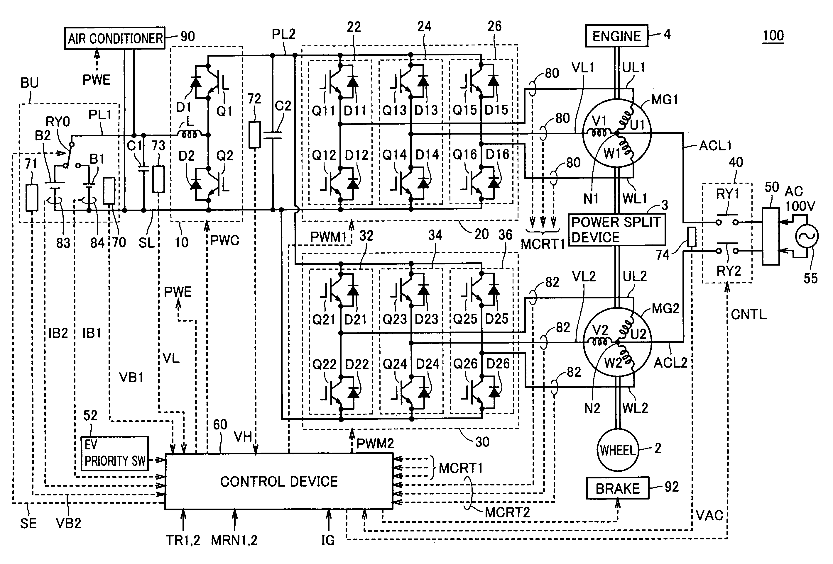
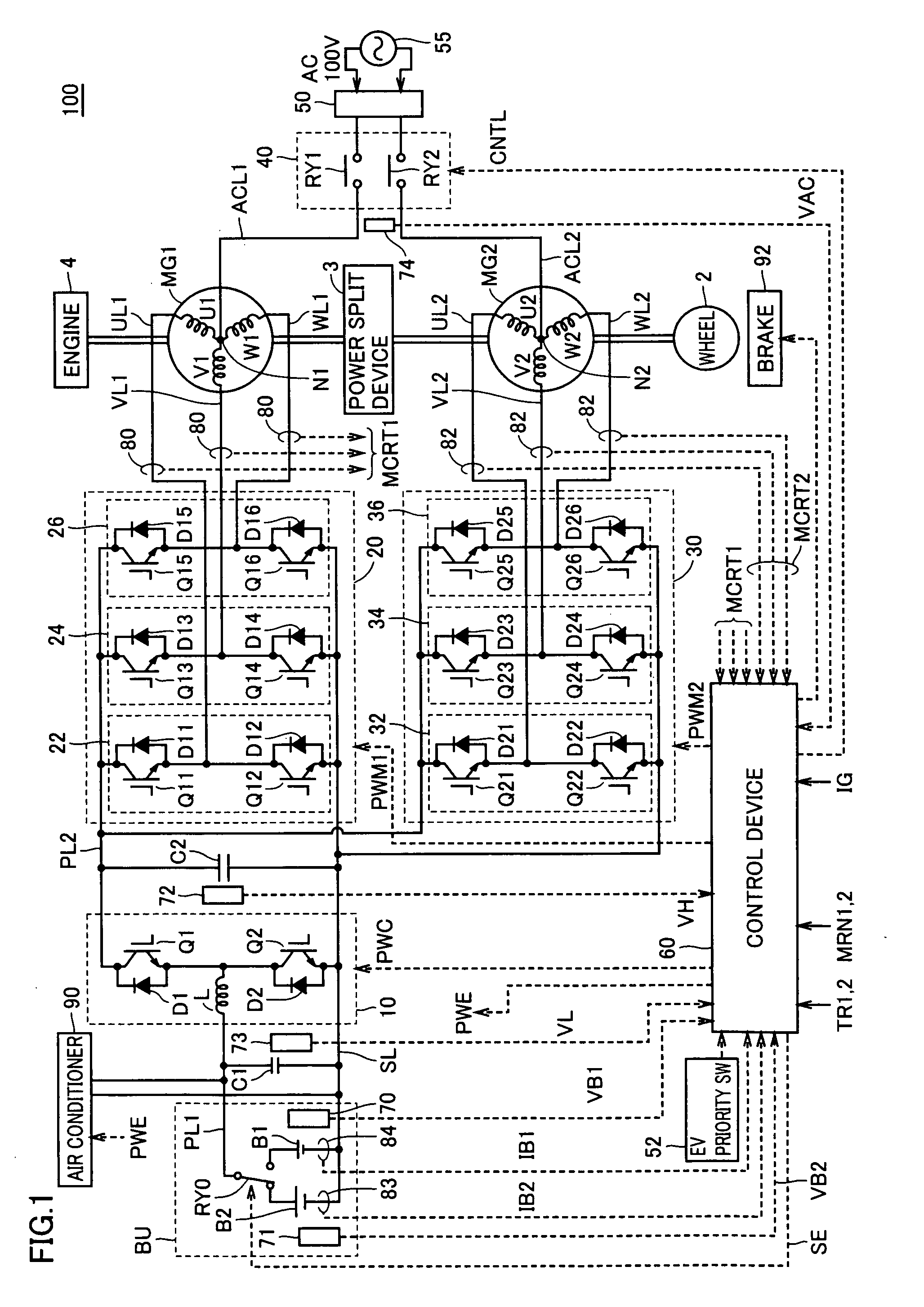
[0052]FIG. 1 is a schematic block diagram of a vehicle according to a first embodiment of the present invention.

[0053]With reference to FIG. 1, vehicle 100 includes a battery unit BU, a voltage step up converter 10, inverters 20, 30, power supply lines PL1, PL2, a ground line SL, U-phase lines UL1, UL2, V-phase lines VL1, VL2, W-phase lines WL1, WL2, motor generators MG1, MG2, an engine 4, a power split device 3, a wheel 2, a brake 92, and an air conditioner 90.

[0054]Vehicle 100 is a hybrid vehicle that uses a motor and an engine in combination for driving the wheel.

[0055]Power split device 3 is a mechanism connected to engine 4 and motor generators MG1, MG2 for distributing motive power among them. For example, a planetary gear mechanism having three rotary shafts of a sun gear, a planetary carrier, and a ring gear may be used for the power split device. The three rotary shafts are connected to rotary shafts of engine 4, motor generators MG1, MG2, respectively. For example, engine ...

second embodiment

[0167]FIG. 13 is a flowchart showing a structure of a process relating to battery switching executed in a second embodiment. The flowchart in FIG. 13 also shows a process executed instead of step S15 in FIG. 9, namely, step S15A.

[0168]Reference is made to FIG. 13. Initially, when the process is initiated, electric power consumed in air conditioner 90 in FIG. 1 is increased to be equal to regenerative electric power generated in motor generator MG2, so that battery power Pb, which is input to and output from battery unit BU, is resultantly made to be 0 in step S21A. Specifically, electric power of the air conditioner may be adjusted such that a current value IB1 sensed by current sensor 84 is made to be 0.

[0169]Successively, the processes in step S22-S24 are executed. Note that the processes in step S22-S24 are the same as those described in FIG. 11, and hence the description thereof will not be repeated.

[0170]When the process in step S24 is completed, electric power consumed in air ...

third embodiment

[0172]In a third embodiment, regenerative braking by motor generator MG2 is temporarily stopped. Therefore, a process in step S15B is performed instead of the process in step S15 in FIG. 9.

[0173]FIG. 14 is a flowchart showing a structure of a process relating to battery switching executed in a third embodiment.

[0174]With reference to FIG. 14, initially in the process in step S15B, regenerative braking by motor generator MG2 is initially stopped, and instead of this, regenerative braking is switched to brake 92 that frictionally brakes wheel 2, so that control is provided to prevent excessive acceleration in a downslope, in step S21B.

[0175]The following processes in steps S22-S24 are the same as those described in FIG. 11, and hence the description thereof will not be repeated.

[0176]In step S25B, braking force of brake 92 caused by friction is reduced, regenerative braking by motor generator MG2 is resumed, and regenerative electric power generated by the regenerative braking is reca...


PUM


Abstract

A power supply device for a vehicle includes a battery (B1) which serves as a first power storage device, a battery (B2) which serves as a second power storage device, a vehicle load, a selection switch (RY0) which selects one of the first and second power storage devices and connects the selected power storage device to the vehicle load, and a control device (60) which, when a current flowing through the selection switch (RY0) is larger than a prescribed value, controls the vehicle load so that the current flowing through the selection switch (RY0) is made smaller than the prescribed value, and switches the selection switch. Preferably, when the control device (60) switches the selection switch (RY0), the control device controls inverters (20, 30) to achieve a balance between electric power generated in a first motor generator (MG2) and electric power consumed in a second motor generator (MG1).

Description

TECHNICAL FIELD[0001]The present invention relates to a power supply device for a vehicle, and particularly to a power supply device for a vehicle, having two power storage devices.BACKGROUND ART[0002]In recent years, attention has been focused on an electric vehicle and a fuel-cell vehicle that use a motor in driving a wheel, a hybrid vehicle that uses a motor and an engine in combination, and other vehicles, as an environmental-friendly vehicle.[0003]For example, an electric vehicle requires a charging device for charging a battery. The charging device may be mounted on a vehicle, or provided at a certain location in a fixed manner.[0004]In the case where the charging device is provided at a certain location in a fixed manner, it is necessary to move the electric vehicle to that place for charging. In other words, providing the charging device in a fixed manner is disadvantageous in that the battery cannot be charged at a place other than the place where the charging device is pro...

Claims


Application Information

Patent Timeline
IPC IPC(8): B60L1/00B60K6/26B60K6/442B60L50/15B60L50/16B60W10/08B60W10/18B60W10/26B60W10/30H02P5/74
CPCB60K1/02Y02T10/6239B60K6/445B60L11/123B60L11/14B60L11/1812B60L11/1814B60L11/1816B60L11/1864B60L15/007B60L2220/54B60W10/08B60W10/184B60W10/26B60W10/30B60W20/00B60W2510/244Y02T10/6217Y02T10/6269Y02T10/641Y02T10/7005Y02T10/7061Y02T10/7077Y02T90/127Y02T90/14B60K6/365Y02T10/7072B60L1/003B60L1/04B60L7/14B60L7/26B60L15/2009B60L15/2054B60L2210/14B60L2210/40B60L2220/56B60L2240/34B60L2240/423B60L2240/429B60L2240/547B60L2240/549B60L50/40B60L50/61B60L50/16B60L53/24B60L58/18B60L58/12B60L58/21B60L58/20Y02T10/62Y02T10/64Y02T10/70Y02T10/72Y02T90/12
Inventor NAKAMURA, MAKOTOOYOBE, HICHIROSAIYANO, TSUYOSHI
Owner TOYOTA JIDOSHA KK
Why Eureka
Try Eureka