Method and apparatus for controlling a lifting magnet supplied with an AC source

a technology of ac source and lifting magnet, which is applied in the direction of electrical equipment, magnetic bodies, load-engaging elements, etc., can solve the problems of arcing between contacts, wear out the insulation of lifting magnets, and the system used to control these lifting magnets remains relatively primitive, so as to reduce the heating of the lifting magnet, reduce the voltage level, and protect the useful life of lifting magnets

Active Publication Date: 2009-06-25
HUBBELL IND CONTROLS
View PDF13 Cites 13 Cited by
  • Summary
  • Abstract
  • Description
  • Claims
  • Application Information

AI Technical Summary

Benefits of technology

[0018]In one embodiment, the control system is configured to increase the useful life of the lifting magnet by reducing voltage spikes in the lifting magnet circuit. During operation, the instantaneous voltage across the magnet typically should not exceed the line voltage, i.e. for a system rated 460 V AC RMS, peak voltage is 460×√=650 V, whereas voltages in prior art systems typically exceed 750 V.
[0026]In one embodiment, the control system is configured to prevent the lifting magnet from sticking to the bottom and walls of magnetizable containers by providing a “Sweep” mode that reduces the voltage levels applied to the lifting magnet during the “Lift” and “Hold” modes.

Problems solved by technology

While lifting magnets have been in common use for many years, the systems used to control these lifting magnets remain relatively primitive.
High voltage spikes cause arcing between the contacts.
In addition, fast rising voltage spikes also eventually wear out the lifting magnet insulation, and the insulation of the cables connecting the lifting magnet to the controller.
Today, magnet control systems are limited by the rectified DC voltage supplying the magnet control (typically 250-350V DC).

Method used


Image

  • Method and apparatus for controlling a lifting magnet supplied with an AC source
  • Method and apparatus for controlling a lifting magnet supplied with an AC source
  • Method and apparatus for controlling a lifting magnet supplied with an AC source

Examples


Embodiment Construction

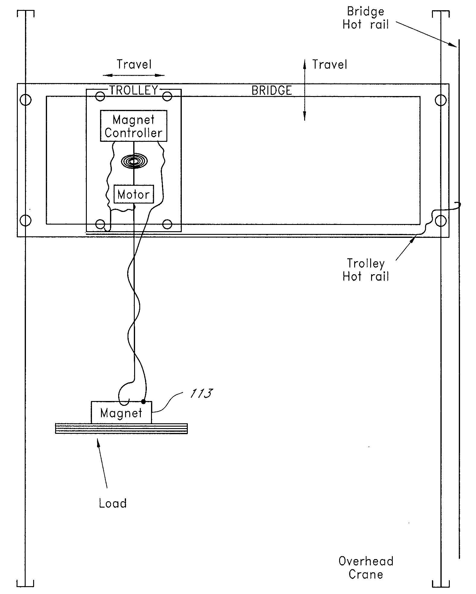
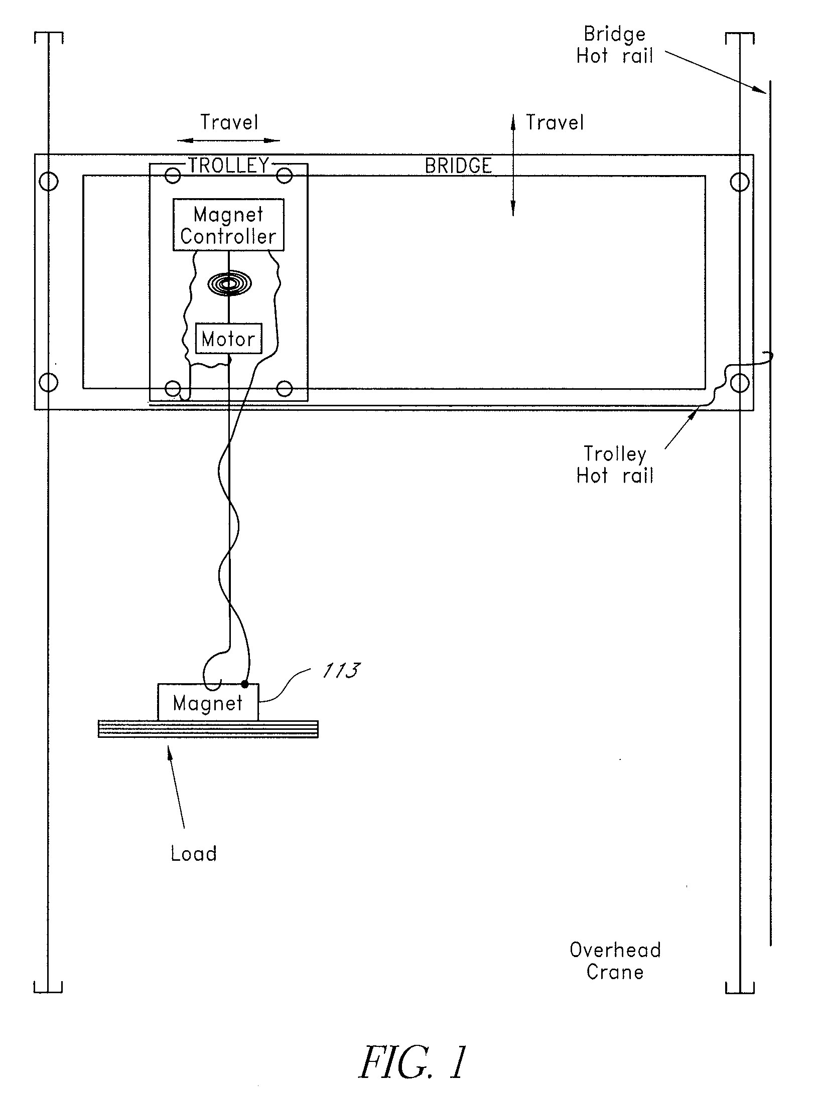
[0041]FIG. 1 shows an overhead crane with lifting magnet 113. The lifting magnet 113 is attached by cables to the magnet controller which controls the lifting magnet 113 from the bridge of the overhead bridge crane.

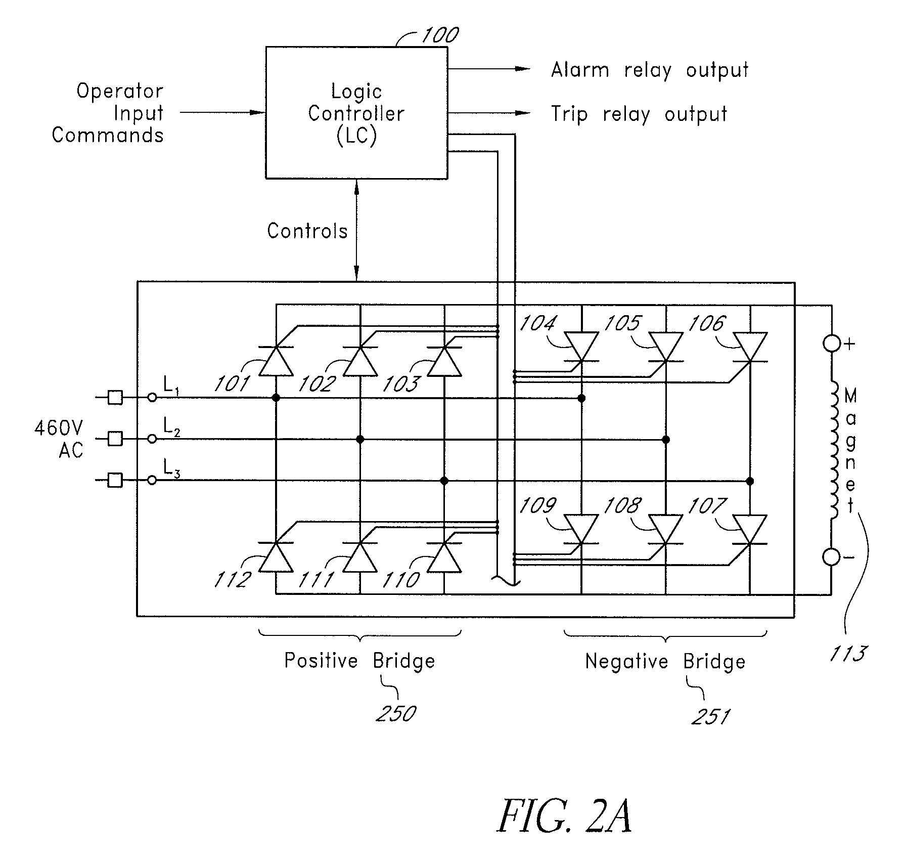
[0042]FIG. 2 shows a lifting magnet controller circuit that includes a Logic Controller (LC) 100. In one embodiment, the LC 100 can be a Programmable Logic Controller (PLC). The LC 100 receives input commands from an operator and provides alarm and trip relay outputs. Outputs from the logic controller 100 are provided to respective switches 101-112. The switches 101-103 and 110-112 are configured in a positive bridge 250 to provide current to the lifting magnet 113 in a first direction, and switches 104-109 are configured in a negative bridge 251 to provide current to the lifting magnet 113 in a second direction. The switches 101-112 can be any type of mechanical or solid-state switch device so long as the devices are capable of switching at a desired speed and can withst...


PUM


Abstract

A magnet controller supplied by an AC source controls a lifting magnet. Two bridges allow DC current to flow in both directions in the lifting magnet. During “Lift”, relatively high voltage is applied to the lifting magnet until it reaches its cold current. Then voltage is lowered. After a desired interval, once the magnet has had time to build its electromagnetic field, voltage is further reduced to prevent the magnet from overheating. The magnet lifting forced is maintained due to the magnetic circuit hysteresis. During “Drop”, reverse voltage is applied briefly to demagnetize the lifting magnet. At the end of the “Lift” and the “Drop”, most of the lifting magnet energy is returned to the line source. A logic controller controls current and voltage of the magnet and calculates the magnet's temperature. In one embodiment, a “Sweep” switch is provided to allow reduction of the magnet power to prevent attraction to the bottom or walls of magnetic rail cars or containers.

Description

REFERENCE TO RELATED APPLICATIONS[0001]The present application claims priority from U.S. Provisional Application No. 61 / 066,121, filed Dec. 19, 2007, titled “METHOD FOR CONTROLLING A LIFTING MAGNET SUPPLIED WITH AN AC SOURCE,” the entire contents of which is hereby incorporated by reference.BACKGROUND[0002]1. Field of the Invention[0003]The present invention relates to a method and apparatus for controlling a lifting magnet of a materials handling machine for which the source of electrical power is an AC power source.[0004]2. Prior Art[0005]Lifting magnets are commonly attached to hoists to load, unload, and otherwise move scrap steel and other ferrous metals. For many years, cranes were designed to be powered by DC sources, and therefore systems used to control lifting magnets were designed to be powered by DC as well. When using a hoist, due to the nature of the overhauling load, the torque and speed of the hoist motor need to be controlled. The traditional approach was to control...

Claims


Application Information

Patent Timeline
Patent Type & Authority Applications(United States)
IPC IPC(8): H01H47/00
CPCH01F7/1811B66C1/08
Inventor MARAVAL, JEAN
Owner HUBBELL IND CONTROLS
Why Eureka
Try Eureka