System And Method For Hydraulic Displacement

a hydraulic displacement and hydraulic system technology, applied in dry docks, climate change adaptation, ship-lifting devices, etc., can solve the problems of ineffective canal locks, ineffective canal locks, and ineffective conventional locks

Inactive Publication Date: 2009-06-25
FOGARTY TERRY
View PDF6 Cites 2 Cited by
  • Summary
  • Abstract
  • Description
  • Claims
  • Application Information

AI Technical Summary

Benefits of technology

[0022]Accordingly it is an object of the present invention to provide an improved system and method for hydraulic displacement which can raise

Problems solved by technology

In fact, conventional locks work so effectively that other solutions have not been sought.
Nevertheless, canal locks are not efficient.
Increasingly, the method of achieving vertical lift via sequential canal locks, which comprise canal sections of approximately 25 metres long having paddle gates at either end, is creating bottlenecks in the inland waterway transport network as the network becomes more popular and more boats use the canals.
Standard canal locks comprise several key challenges, not only for those sailing the boats, but also for the environment.
This is a substantial amount of water which is lost each time a boat passes through a lock.
Generally, there are other environmental problems associated with canal locks relating to the silting up of the locks due to the stagnation of water.
Insufficient or irregular water flow causes silting of the canal channel.
Generally, flights of locks take a relatively long time to transit due to the limitations in vertical height that each lock can provide as well as the duration of the transit which involves opening and closing paddle gates against the water in the locks themselves.
The cost of building the boat lift and completing the connecting canal infrastructure at Strepy-Thieu in Belgium was reported as costing in excess of 647 million euros.
In fact, the boat lift system is extremely complicated to operate and to maintain which greatly limits it to high water traffic environments.
Clearly, these systems for connecting canals at different elevations are very complex and expensive to construct and any cost effective alternative which is more effective and efficient to implement will be very attractive to the i

Method used


Image

  • System And Method For Hydraulic Displacement
  • System And Method For Hydraulic Displacement
  • System And Method For Hydraulic Displacement

Examples


Embodiment Construction

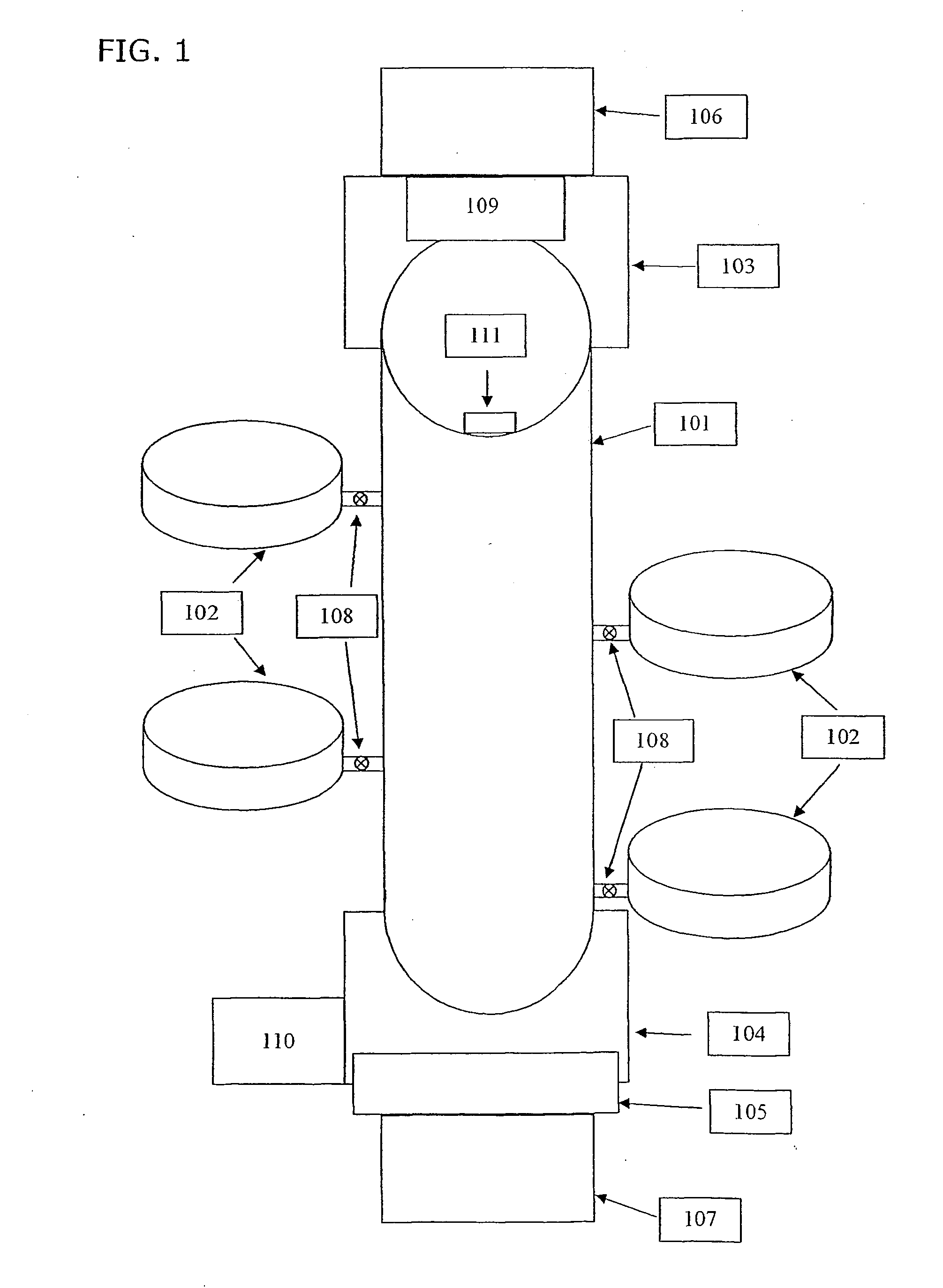
[0071]Referring now in detail to the drawings and in particular FIG. 1 thereof, therein illustrated is a schematic of the hydraulic displacement system according to the current invention.

[0072]The following description makes full reference to the detailed features according to different embodiments as outlined in the objects of the invention.

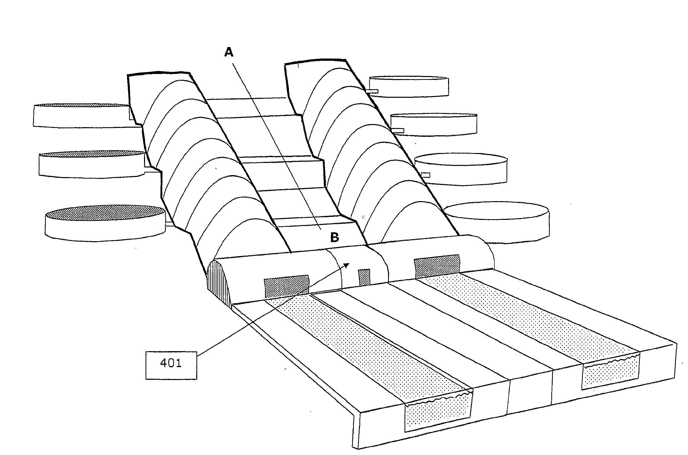
[0073]The system comprises a central transit tube (101) which has connected to it a sequence of side storage tanks (102). In the application for an improved canal lock, the hydraulic system connects two canals at different elevations.

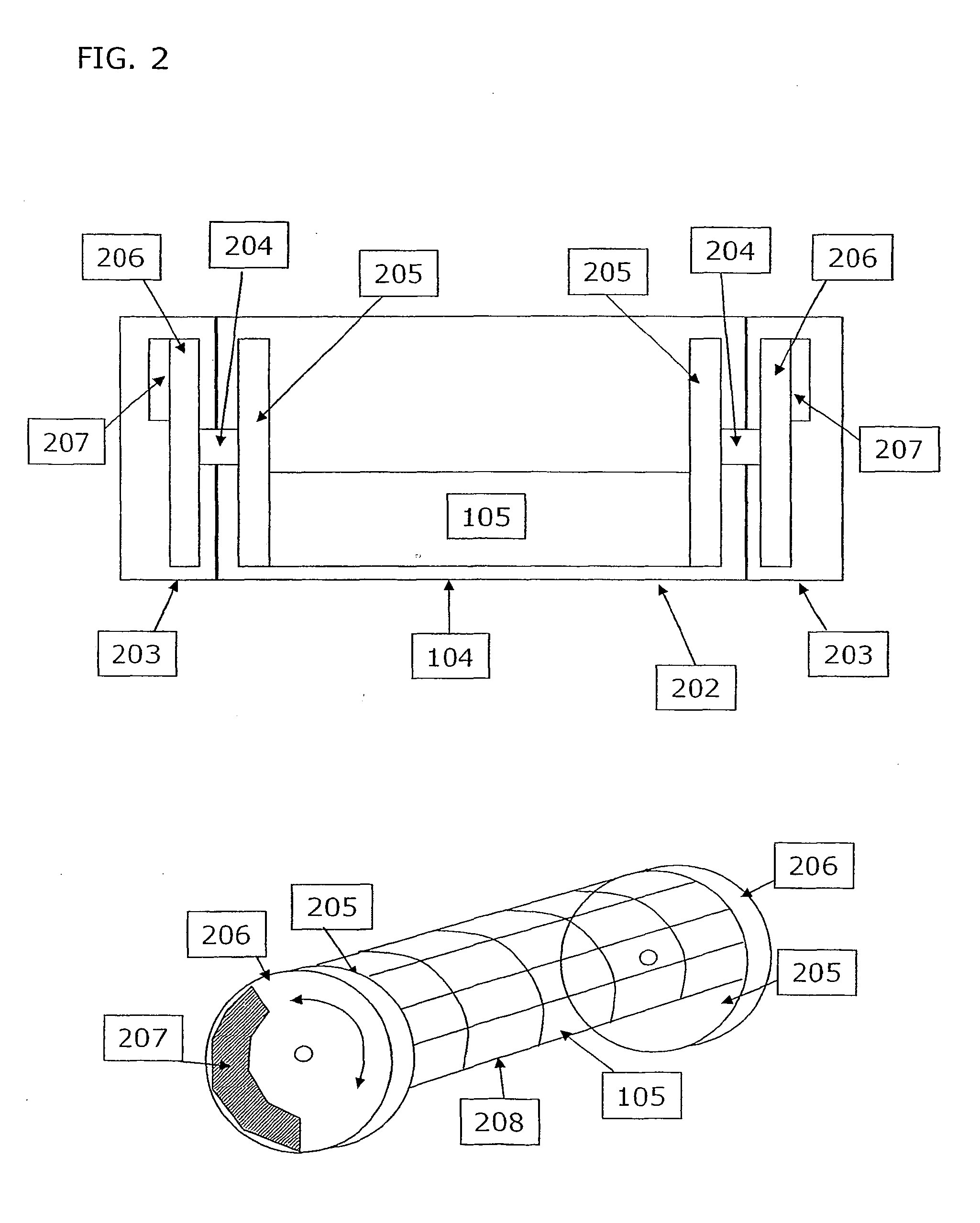
[0074]The system further comprises a lower entry structure (104) and an upper entry structure (103). The lower entry structure (104) further comprises a gate (105) which can be opened or closed to allow boats or floating pontoons to enter or leave the hydraulic displacement system.

[0075]At the lower end of the system is a lower waterway (107) which is separated from the transit tube by the gate (105) and at the high...


PUM


Abstract

A system and method for hydraulic displacement is described which can provide an improved method for raising or lowering a fluid level. The system and method has direct application to inland waterway transport and in particular to canal locks where canal boats traverse inclines through a series of locks. In addition, the invention can provide the access to a marina, which may be raised up above sea level or behind a sea wall defence. The method enables the formation of an improved hydraulic displacement lock capable of a greater vertical displacement with greatly reduced flow of fluid through the lock. The hydraulic displacement lock comprises an enclosed central channel, having sequential fluid storage tanks connected to the central channel. When the central channel is closed at its lower end, opening and closing connecting channels to the sequential storage tanks allows fluid to flow under the force of gravity into or out of the central channel, thereby raising or lowering the level of fluid.

Description

BACKGROUND OF THE INVENTION[0001]The invention relates to a system and method for hydraulic displacement. More particularly, it relates to a system and method for raising or lowering a fluid level in a central cavity, which can work using active pumping or under gravity without requiring any power. In particular, the invention has direct application to inland waterway transport wherein this system and method for hydraulic displacement can be used to create a highly efficient and effective way to raise or lower a boat between different water levels. In addition, the invention can provide sea or lake-going boats with an improved access to a marina, which may be raised up above sea level and or behind a sea wall defence.[0002]Generally, inland waterway networks have been well established over many hundreds of years and methods to raise boats over inclines using standard locks are known. In fact, conventional locks work so effectively that other solutions have not been sought. Neverthel...

Claims


Application Information

Patent Timeline
IPC IPC(8): E02C5/00
CPCE02C1/02Y02A10/30
Inventor FOGARTY, TERRY
Owner FOGARTY TERRY
Why Eureka
Try Eureka