Microminiature x-ray tube with triode structure using a NANO emitter

a triode and x-ray tube technology, applied in the direction of x-ray tubes, x-ray tube cathode assemblies, nuclear engineering, etc., can solve the problems of difficult to manufacture x-ray tubes at a low cost, complicated operation process, and high cost, and achieve high electrical characteristics, structural stability, and high electrical characteristics. , the effect of promoting electron beam focusing

Active Publication Date: 2011-05-19
ELECTRONICS & TELECOMM RES INST
View PDF0 Cites 17 Cited by
  • Summary
  • Abstract
  • Description
  • Claims
  • Application Information

AI Technical Summary

Benefits of technology

[0022]As described above, a microminiature X-ray tube with a triode structure using a nano emitter according to the present invention has the following advantages:
[0023]First, a field emission region can be increased as much as possible by nano emitters fine-patterned in a cathode so that an emission current per unit area can be increased as much as possible, and high electrical characteristics, reliability, and structural stability can be secured by a cover and a bonding material.
[0024]Second, gate holes having a macro structure can be formed in a gate so that electron beams can be focused by the gate without a separate focusing electrode and a leakage current can be prevented from occurring on the gate.
[0025]Third, an auxiliary electrode can be formed on a top or an inner surface of the cover applied for structural stability to additionally promote the electron beam focusing.
[0026]Fourth, the present invention can be directly applied to existing X-ray tubes which are currently available without separately changing the structures, so that it is cost-effective.
[0027]Fifth, since an output amount per each X-ray tube which is output according to current switching can be controlled to be the same amount, the lifetime of the X-ray tube can be lengthened.

Problems solved by technology

In addition, it is difficult to manufacture the X-ray tube at a low cost.
Both the stem and the output window need to be soldered, and thus manufacture thereof is very time-consuming.
In addition, the X-ray tube usually requires different soldering materials for both the stem and the output window so that the operation process becomes complicated, which makes mass production difficult.
As a result, the fixing portion between the tungsten coil and the cathode pins becomes loose, which leads to deterioration of properties and lifetime of the filament so that the reliability may be lost.
To detail this, it employs a technique of applying a high voltage to the anode to accelerate electrons when the electrons are emitted from the cathode, which thus makes it difficult to focus and control the electrons.
Further, since the thermionic emission from the filament is omni-directional, the efficiency with regard to an amount of electrons actually reaching the anode becomes extremely low.
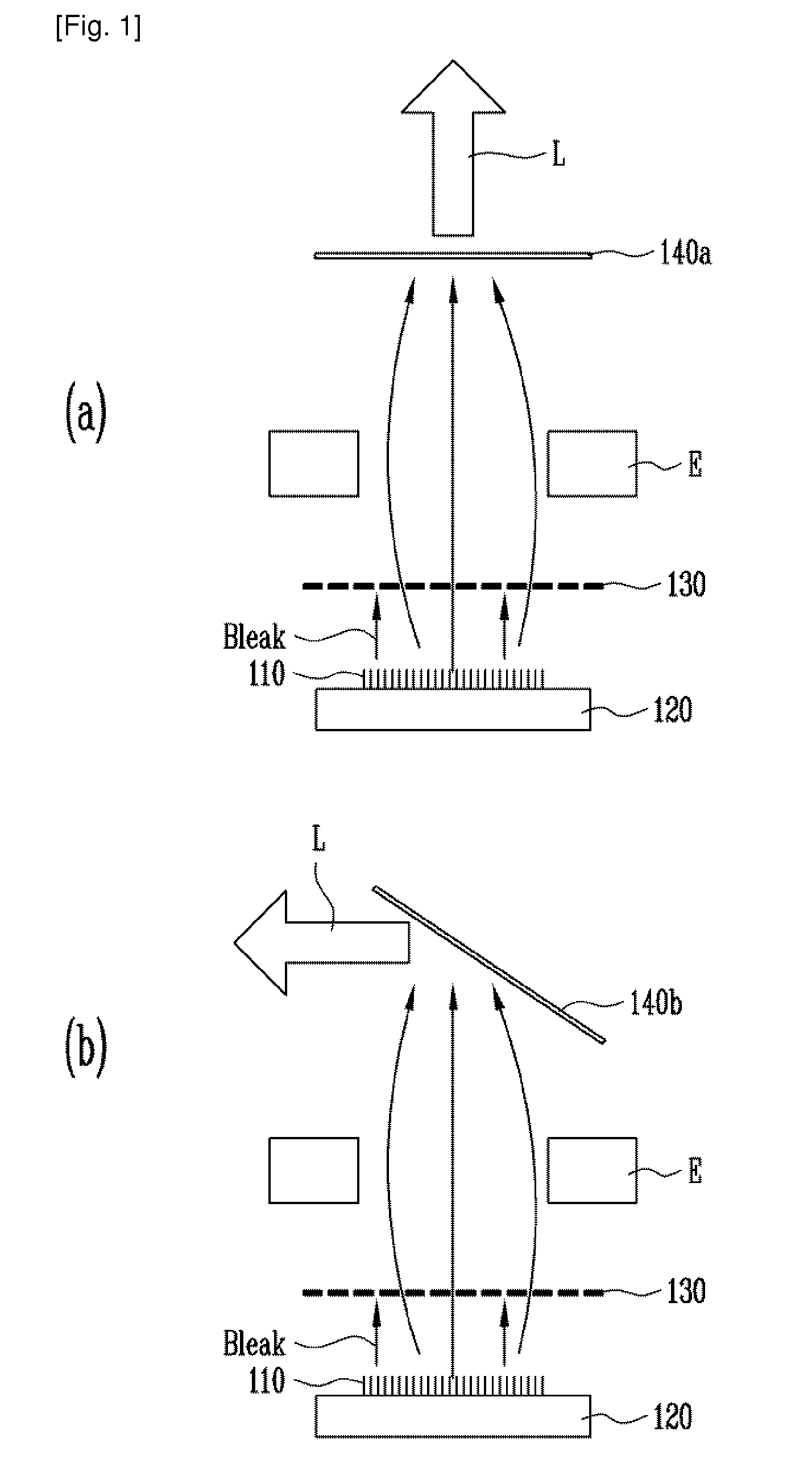
However, according to the conventional X-ray tube using nano emitters, focusing the electron beams is adjusted by the voltage to be applied to the focusing electrodes E, so that another separate focusing electrode E must be disposed when the electron beam focusing needs to be implemented or enhanced, which thus results in a complicated structure and a difficult manufacturing process.

Method used


Image

  • Microminiature x-ray tube with triode structure using a NANO emitter
  • Microminiature x-ray tube with triode structure using a NANO emitter
  • Microminiature x-ray tube with triode structure using a NANO emitter

Examples


Embodiment Construction

[0046]Hereinafter, exemplary embodiments of the present invention will be described in detail with respect to the microminiature X-ray tube with a triode structure using the nano emitter. However, the present invention is not limited to the exemplary embodiments disclosed below, but can be implemented in various types. Therefore, the present exemplary embodiments are provided for complete disclosure of the present invention and to fully inform the scope of the present invention to those ordinarily skilled in the art.

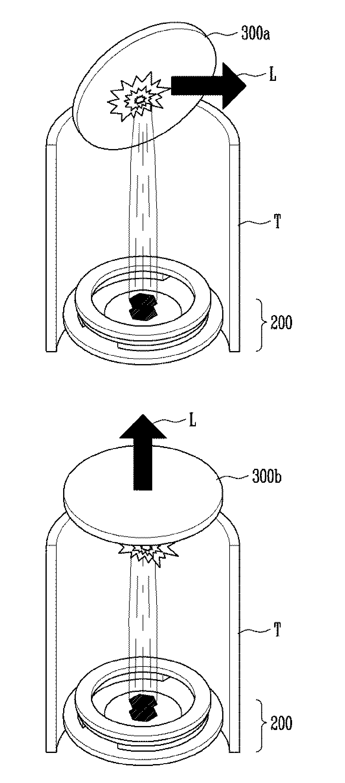
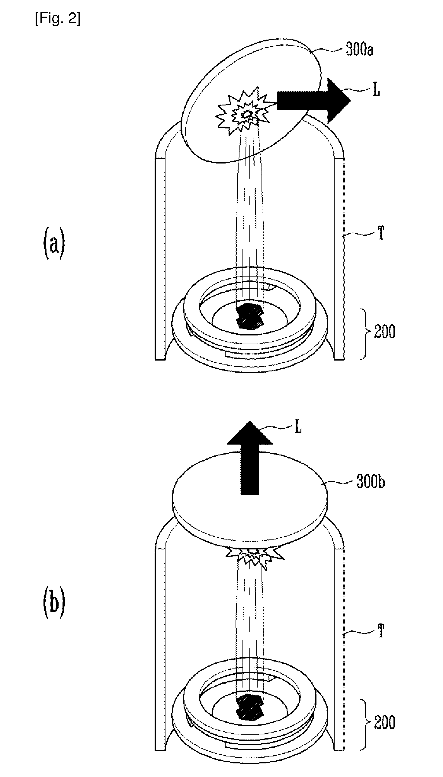
[0047]FIGS. 2A and 2B schematically illustrate a microminiature X-ray tube with a triode structure using a nano emitter according to an exemplary embodiment of the present invention. FIG. 2A illustrates a reflective type structure and FIG. 2B illustrates a transmissive type structure.

[0048]Referring to FIGS. 2A and 2B, in the microminiature X-ray tube with a triode structure using a nano emitter according to an exemplary embodiment of the present invention, when electron...


PUM


Abstract

A microminiature X-ray tube with a triode structure using a nano emitter is provided, which can increase a field emission region as much as possible by means of nano emitters fine-patterned in a cathode to not only increase an emission current per unit area as much as possible but secure high electrical characteristics, reliability, and structural stability by means of a cover and a bonding material. In addition, gate holes having a macro structure can be formed in the gate to promote electron beam focusing by means of the gate without using a separate focusing electrode and to prevent a leakage current from occurring on the gate. Further, an auxiliary electrode can be formed on a top or an inner surface of a cover applied for structural stability to further promote the electron beam focusing and to control the output amounts per individual X-ray tubes output according to current switching to be equal to each other.

Description

TECHNICAL FIELD[0001]The present invention relates to a microminiature X-ray tube with a triode structure using a nano emitter such as carbon nano tube (CNT), and more particularly, to a microminiature X-ray tube with a triode structure which uses the nano emitter to secure high electrical characteristics, reliability, and structural stability.BACKGROUND ART[0002]X-ray tubes are typically employed as X-ray sources for medical apparatuses, industrial measuring apparatuses and so forth, and have recently been employed as X-ray fluorescences (XRFs) and X-ray sources of electrostatic neutralization apparatuses, use of which has largely increased.[0003]A typical X-ray tube includes a ceramic stem (also referred to as a vacuum tube) with cathode pins vertically disposed and an output window with a target metal deposited on its bottom surface, which are supported by ceramic valves and soldered to each other, and focusing electrodes are disposed along an inner circumferential surface of the...

Claims


Application Information

Patent Timeline
Patent Type & Authority Applications(United States)
IPC IPC(8): H01J35/04
CPCH01J35/065H01J35/14H01J35/16H01J2235/186H01J2235/068H01J2235/087H01J2235/164H01J2235/062H01J35/116H01J35/147H01J35/186H01J2201/30469H01J35/064
Inventor KIM, DAE JUNSONG, YOON HOJEONG, JIN WOO
Owner ELECTRONICS & TELECOMM RES INST
Why Eureka
Try Eureka