Rotary tablet press

a tablet press and rotary technology, applied in the field of rotary tablet presses, can solve the problems of rather complex design and consequently high cos

Inactive Publication Date: 2005-12-06
COURTOY
View PDF12 Cites 18 Cited by
  • Summary
  • Abstract
  • Description
  • Claims
  • Application Information

AI Technical Summary

Benefits of technology

[0008]In this way, the clamping force may be applied directly between the turret and the drive shaft, without the need for mechanically transferring the clamping force from the stationary housing of the tablet press to the rotary system.
[0009]A rather large actuator may be accommodated in the turret, thereby ensuring the provision of sufficient clamping force for the coupling, and the employment of a pneumatic actuator minimizes the risk that harmful fluid leaks into areas containing product.
[0016]In a further embodiment, the actuator is driven by means of pressurized air supplied from the housing via tubing comprising a rotary coupling. In this way, the connection between the air supply and the rotary system may be maintained during rotation of the turret, and no manual or automatic connection between the air supply and the rotary system has to be performed before the coupling may be operated in order to remove the turret from the drive shaft.
[0018]In a further embodiment, each coupling part is provided with a coaxially arranged toothed ring, said toothed rings being mutually engageable upon connection of the two coupling parts. The engagement between the toothed rings permits the transmission of sufficient torque from the drive shaft to the turret.

Problems solved by technology

However, due to the additional intermediate spindle portion with associated bearings carrying the die table, this design is rather complex and consequently costly.

Method used


Image

  • Rotary tablet press
  • Rotary tablet press
  • Rotary tablet press

Examples


Embodiment Construction

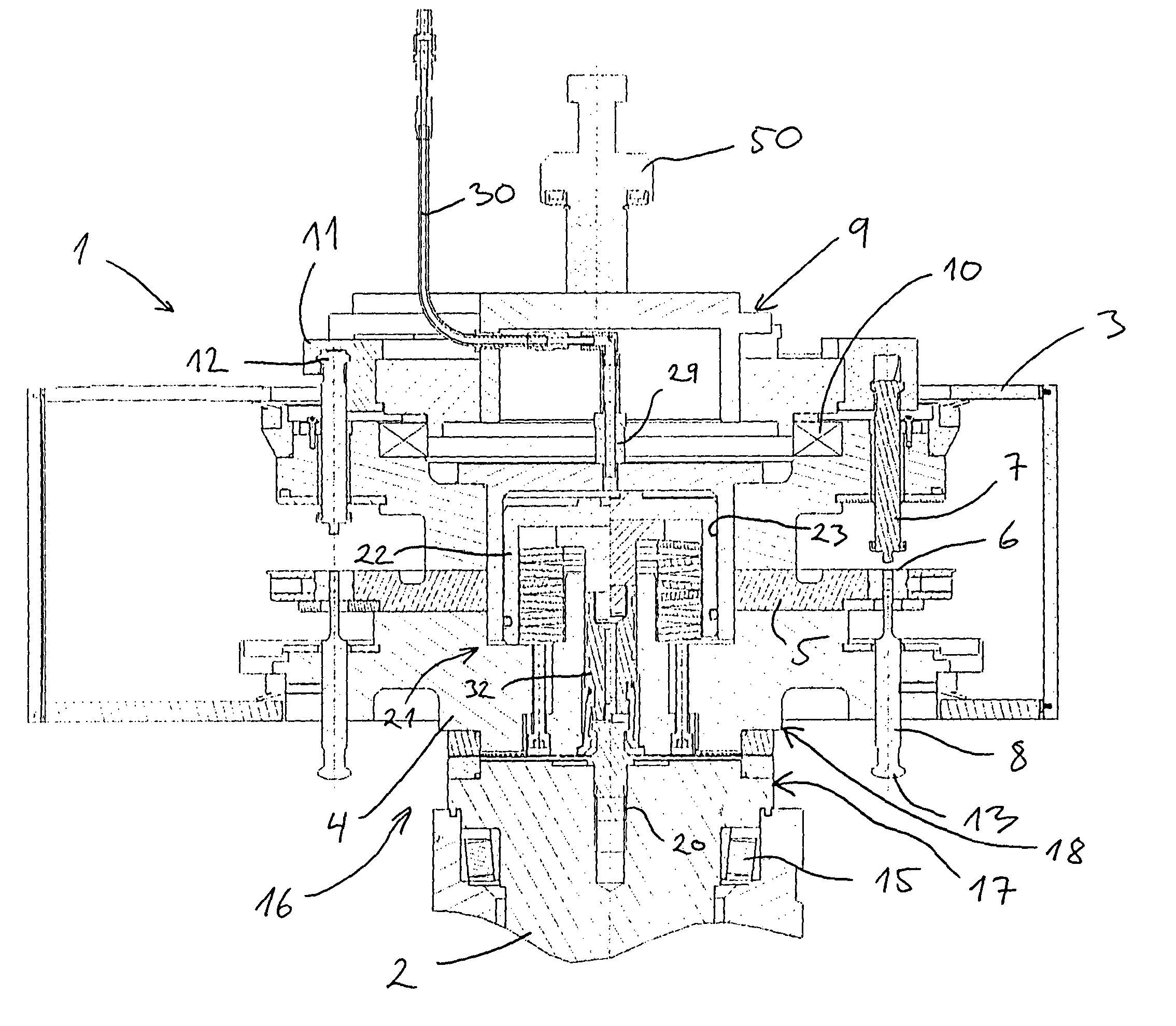
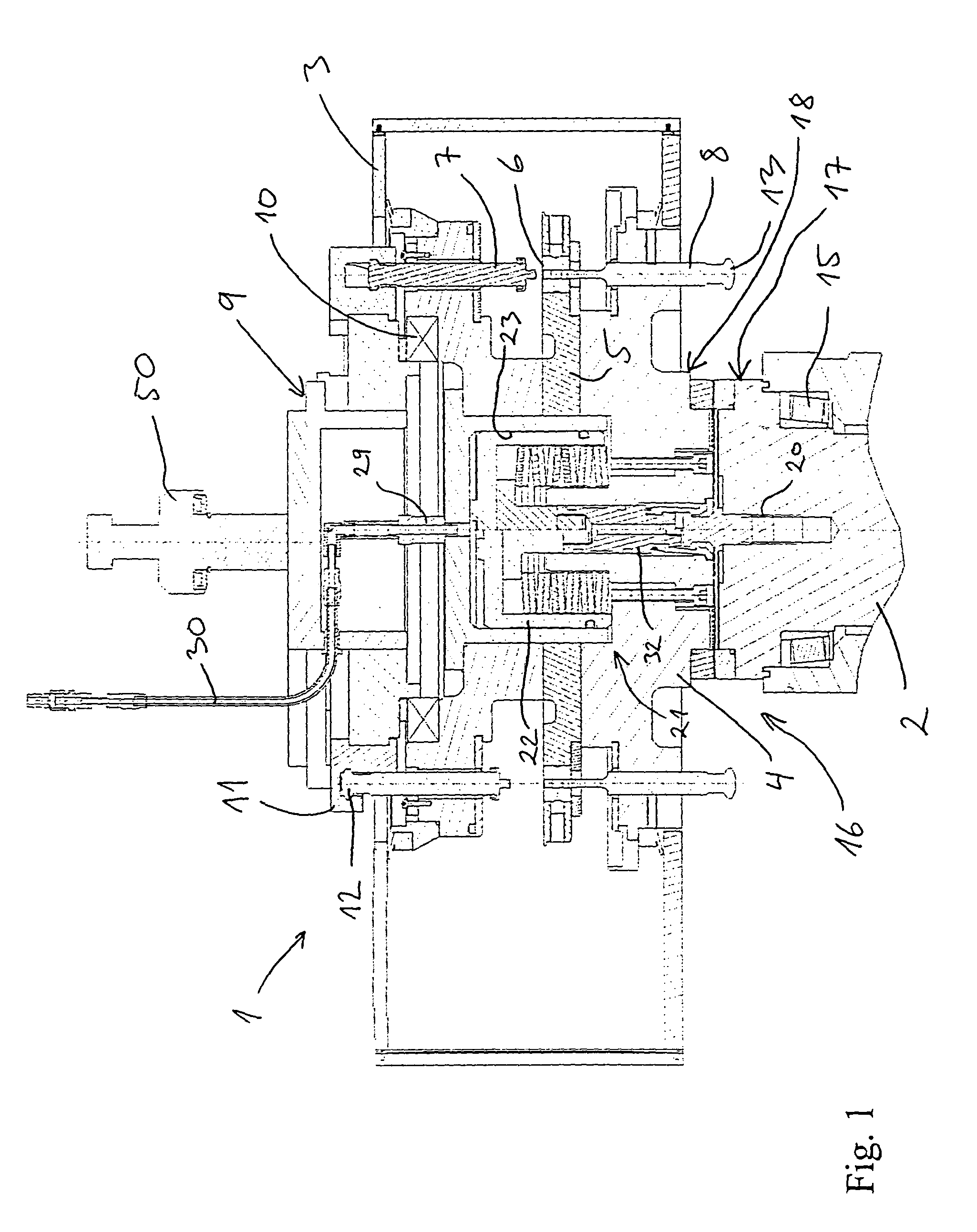
[0027]FIG. 1 shows a compression unit 1 and part of a drive shaft 2 of a rotary tablet press for compression of a feedstock in the form of powder or granular material into tablets, compacts or the like. The tablet press is of a type suitable for use in the pharmaceutical industry, but the press according to the invention may as well be a so-called industrial press employed in the production of a variety of different products, such as vitamins, pet food, detergents, explosives, ceramics, batteries, balls, bearings, nuclear fuels, etc.

[0028]The compression unit 1 is detachably arranged in a not shown housing of the tablet press and comprises a stationary casing 3, in which is arranged a rotary turret 4. The turret 4 comprises a die table 5, in which a number of dies 6 are arranged circumferentially. Each die 6 is associated with an upper punch 7 and a lower punch 8 guided in the turret 4 in order to compress material in the die 6. The turret 4 is arranged rotatably in the casing 3 and...


PUM

PropertyMeasurementUnit
axial displacementaaaaaaaaaa
displacementaaaaaaaaaa
clamping forceaaaaaaaaaa

Abstract

A rotary tablet press comprises a rotary system constituted by a turret and a drive shaft arranged in a housing for rotation of the turret. The turret includes a die table and a number of punches are guided in the turret. The turret is connectable to the drive shaft by a coupling including a first coupling part and a second coupling part which are interconnectable by clamping elements engageable between the coupling parts by at least one pneumatic actuator situated in the rotary system.

Description

CROSS-REFERENCE TO RELATED APPLICATIONS[0001]Not ApplicableSTATEMENT REGARDING FEDERALLY SPONSORED RESEARCH OR DEVELOPMENT[0002]Not ApplicableREFERENCE TO A MICROFICHE APPENDIX[0003]Not ApplicableBACKGROUND OF THE INVENTION[0004]The present invention relates to a rotary tablet press comprising a turret and a drive shaft arranged in the housing for rotation of the turret.[0005]U.S. Pat. No. 5,004,413 discloses a rotary tablet press comprising a die table carried by bearings mounted on an intermediate axially extending portion of a spindle fixed stationary on the machine frame. The die table is driven through inter-engaging drive dogs by a pulley carried by bearings mounted on a lower, fixed end portion of the spindle. An upper end portion of the spindle is attached to a machine upper frame and comprises a fluid-operable piston which is downward displaceable axially in the spindle to engage an upper end face of the intermediate spindle portion in order to press a lower end face of thi...

Claims


Application Information

Patent Timeline
Patent Type & Authority Patents(United States)
IPC IPC(8): B30B11/08B30B15/00
CPCB30B11/08B30B15/0023B30B15/028B30B15/026Y10T29/4995
Inventor BOECKX, JURGENCHRISTIAENS, DIRKVOGELEER, JAN
Owner COURTOY
Why Eureka
Try Eureka