Hybrid Vehicle Having Torsional Coupling Between Engine Assembly And Motor-Generator

a technology of torsional coupling and hybrid vehicle, which is applied in the direction of electric propulsion mounting, couplings, transportation and packaging, etc., can solve the problems of reducing the shock transmission between the internal combustion engine and the internal combustion engine, and achieve the effect of reducing shock or vibration, reducing shock and/or vibration

Active Publication Date: 2009-07-02
BYD CO LTD
View PDF14 Cites 6 Cited by
  • Summary
  • Abstract
  • Description
  • Claims
  • Application Information

AI Technical Summary

Benefits of technology

[0028]The torsional coupling may include a first gasket disposed between the inner sideboard and a first side of the torsion plate, and a second gasket disposed between the outer sideboard and a second side of the torsion plate. The first and second gaskets are formed of a deformable material to reduce shock or vibration transmitted between internal combustion engine and hollow rotor shaft by the torsion plate. The shock absorbing elements are configured to reduce shock and / or vibration cause by operation of the internal combustion engine and the first motor / generator. The shock absorbing elements may be coil springs or compression springs and / or may be formed of compressible or resilient material.

Problems solved by technology

The torsion distribution assembly may also dampen any shock transmitted between the internal combustible engine and the motor-generator.

Method used


Image

  • Hybrid Vehicle Having Torsional Coupling Between Engine Assembly And Motor-Generator
  • Hybrid Vehicle Having Torsional Coupling Between Engine Assembly And Motor-Generator
  • Hybrid Vehicle Having Torsional Coupling Between Engine Assembly And Motor-Generator

Examples


Embodiment Construction

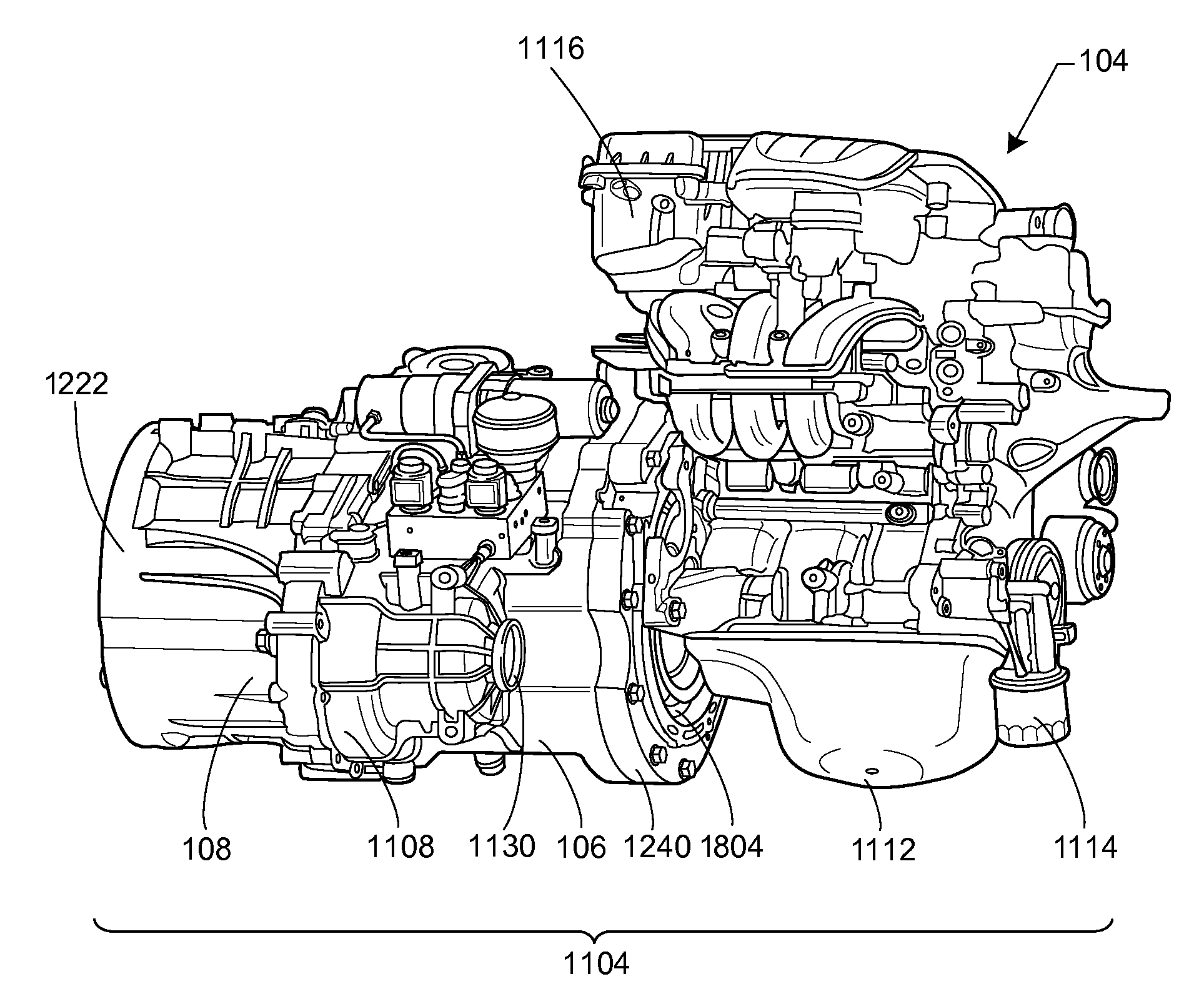
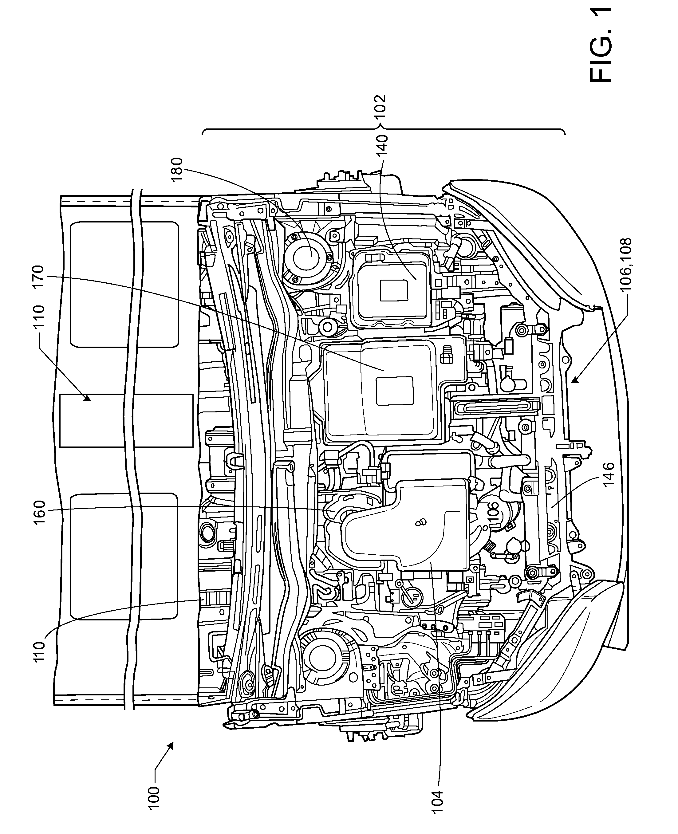
[0077]FIG. 1 shows the front engine compartment 100 of a motor vehicle equipped with a multi-mode hybrid power system 102. The hybrid power system 102 includes an internal combustible engine 104, an electric motor-generator 106, an electric traction motor 108, and a battery pack 110. The battery pack 110 may be located within a floorboard compartment and may not be visible in the view of FIG. 1. The hybrid power system 102 may also include other components, such as, a power inverter assembly 140, radiator146, intake manifold 160, control system enclosure 170, shock absorber towers 180, and other components, such as, various filters, fuel injection system, master cylinder assembly, water pump, electronic ignition housing, etc.

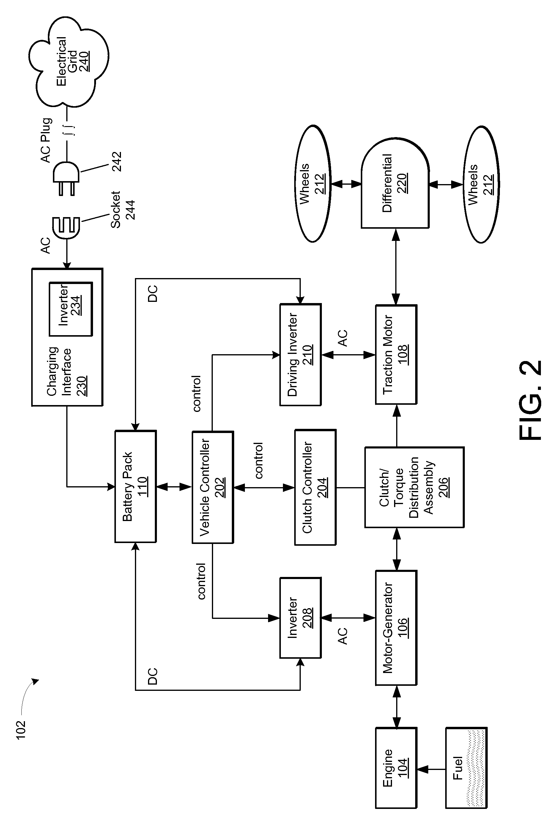
[0078]FIG. 2 shows a block diagram of the multi-mode or hybrid power system 102, which includes a vehicle controller 202, a clutch controller 204, a clutch assembly or torque distribution assembly 206, a first inverter 208, a driving inverter 210, the engine 104...


PUM


Abstract

A hybrid vehicle has a power system with a torsional coupling. The power system includes a battery system for receiving, storing and providing electrical power, an internal combustion engine configured to provide rotational power through a flywheel, a first motor-generator, a second motor-generator, a control system, and a torsional coupling. The torsional coupling may absorb rotational shock caused by angular or rotational speed differences between the engine and the first motor-generator. The torsional coupling includes a driven plate assembly, a cover assembly and an interconnecting plate assembly. The interconnecting plate assembly may include a plurality of shock absorbing elements that absorb shock and vibration between the engine and the motor-generator.

Description

CROSS-REFERENCE TO RELATED APPLICATIONS[0001]This application claims the benefit of priority to the following applications:[0002]1) Chinese Patent Application No. 2008-10185948.3 (docket no. ______) filed on Dec. 13, 2008, entitled “______,”[0003]2) Chinese Patent Application No. 2008-10185949.8 (docket no. ______) filed on Dec. 13, 2008, entitled “______,”[0004]3) Chinese Patent Application No. 2008-10185950.0 (docket no. ______) filed on Dec. 13, 2008, entitled “______,”[0005]4) Chinese Patent Application No. 2008-10185951.5 (docket no. ______) filed on Dec. 13, 2008, entitled “______,”[0006]5) Chinese Patent Application No. 2008-10185952.X (docket no. ______) filed on Dec. 13, 2008, entitled “______,”[0007]6) Chinese Patent Application No. 2008-10217019.6 (docket no. 081484) filed on Oct. 11, 2008, entitled “A Hybrid Power Driving System and its Control Method,”[0008]7) Chinese Patent Application No. 2008-10217015.8 (docket no. 081322) filed on Oct. 11, 2008, entitled “A Hybrid P...

Claims


Application Information

Patent Timeline
Patent Type & Authority Applications(United States)
IPC IPC(8): B60K6/50B60L50/10
CPCB60K1/02Y10S903/912B60K6/405B60K6/442B60L2240/421B60L2240/441B60W10/02B60W10/06B60W10/08B60W10/26B60W20/00B60W2510/0638B60W2510/081F16D3/66F16D48/02Y02T10/6234Y02T10/6269Y02T10/6286Y02T10/642Y10S903/946B60K6/387F16D2500/1024F16D2500/1066F16D2500/3024F16D2500/30401F16D2500/7027F16D2500/70406F16D2500/7041Y02T10/62Y02T10/64B60W20/40
Inventor LUO, HONGBINREN, YIYANG, SHENGLINWANG, TAOLIU, YAN
Owner BYD CO LTD
Why Eureka
Try Eureka