
System and Method for Performing High Flow Rate Dispensation of a Chemical onto a Photolithographic Component

a photolithographic component and high flow rate technology, applied in the field of semiconductor manufacturing, can solve the problems of increasing the rate of pattern collapse, cd uniformity of components, and faulty or defective components manufactured with such components, so as to reduce the harmful effects of manufacturing, the effect of high flow ra

Inactive Publication Date: 2009-07-02
TOPPAN PHOTOMASKS INC
View PDF4 Cites 7 Cited by
  • Summary
  • Abstract
  • Description
  • Claims
  • Application Information

AI Technical Summary

Benefits of technology

[0008]In accordance with the present disclosure, the disadvantages and problems associated with the manufacture of a photolithographic component have been reduced or eliminated. In a particular embodiment, a chemical may be dispensed by a nozzle onto a photolithographic component in order to reduce harmful effects occurring on the surface of the component.
[0009]In accordance with one embodiment of the present disclosure, a method for dispensation of a chemical onto a photolithographic component includes providing a photolithographic component in a manufacturing tool, and positioning the component at a predetermined distance from a nozzle. The nozzle dispenses a chemical on the surface of the photolithographic component at a high flow rate such that the rate of flow may reduce harmful effects occurring on the surface of the component.
[0010]In accordance with another embodiment of the present disclosure, an apparatus for dispensation of a chemical onto a photolithographic component includes a nozzle operable to dispense the chemical at a high flow rate on the surface of the photolithographic component such that the rate of flow may reduce the occurrence of harmful effects on the surface of the component. The apparatus also includes a substrate holder operable to position the photolithographic component at a predetermined distance from the nozzle.
[0011]In accordance with an additional embodiment of the present disclosure, a method for performing high flow rate development of a photolithographic component includes providing a photolithographic component in a manufacturing tool, the photolithographic component including a resist layer having a pattern imaged therein. The photolithographic component is positioned at a predetermined distance from a nozzle operable to dispense a developer solution. The developer solution is dispensed on the surface of the resist layer at a high flow rate such that the rate of flow may ensure uniform development of the pattern across the surface of the component.

Problems solved by technology

If measures are not taken to ensure adequate uniformity of CD across a photolithographic component, ICs manufactured with such components may prove faulty or defective.
These by-products may create harmful effects known as microloading effects that can cause problems with CD uniformity across the component.
This technique requires that the flow rate of the developer and rinse stay identical, which may increase the rate of pattern collapse.
Additionally, the technique requires use of a large amount of chemicals (both the developer and the rinse) and requires a develop time that depends on the scanning speed of the nozzle.
This technique, however, does not provide for the removal of used liquid agent, which does not prevent microloading effects from occurring.
Additionally, a rinse solution must be applied from a separate nozzle, which increases develop time.

Method used


Image

  • System and Method for Performing High Flow Rate Dispensation of a Chemical onto a Photolithographic Component
  • System and Method for Performing High Flow Rate Dispensation of a Chemical onto a Photolithographic Component
  • System and Method for Performing High Flow Rate Dispensation of a Chemical onto a Photolithographic Component

Examples


Embodiment Construction

[0019]Preferred embodiments of the present disclosure and their advantages are best understood by reference to FIGS. 1 through 6, where like numbers are used to indicate like and corresponding parts.

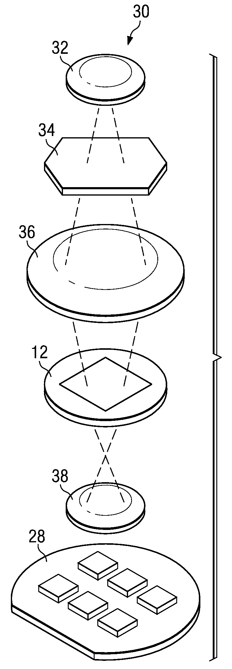
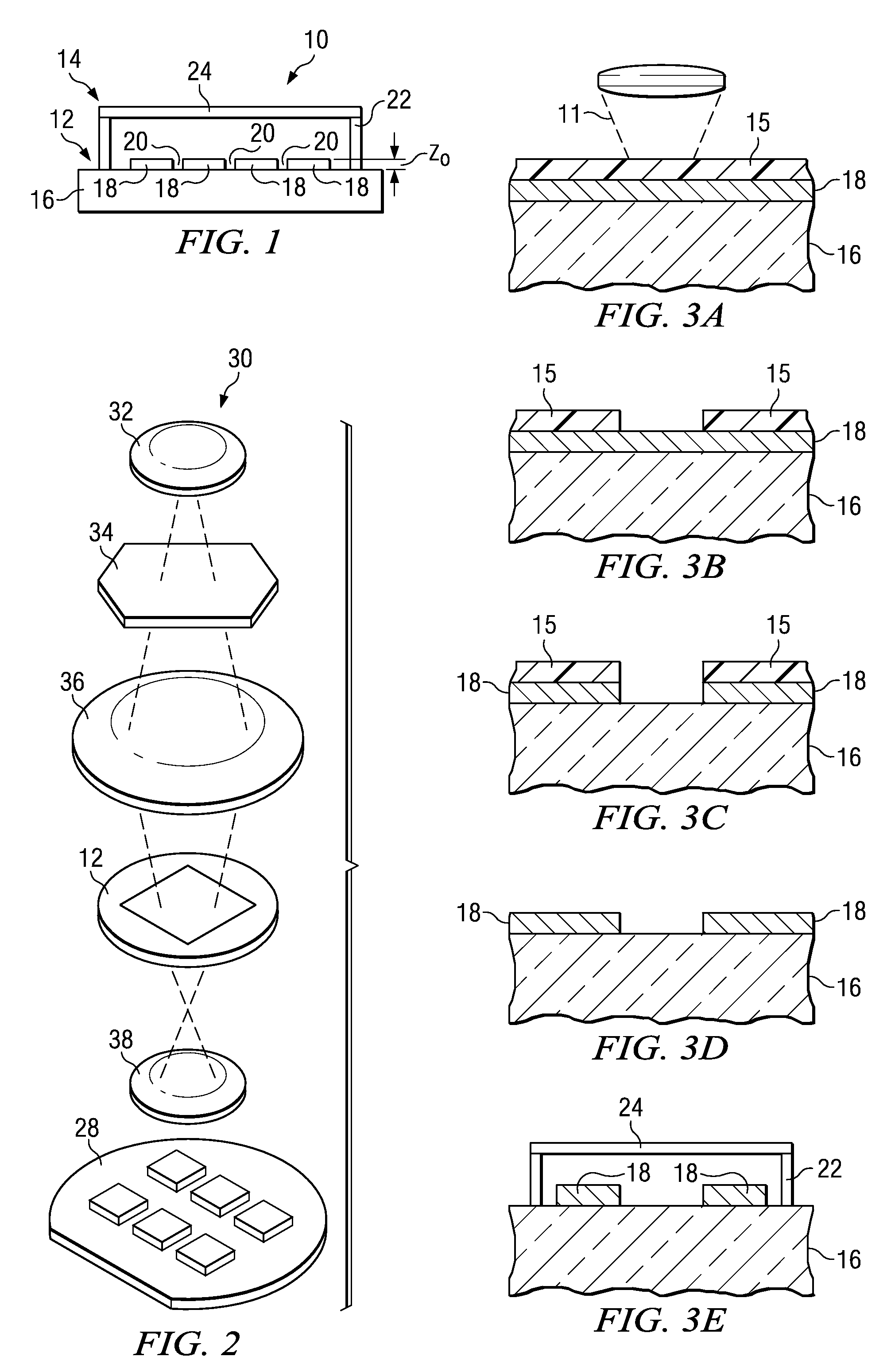
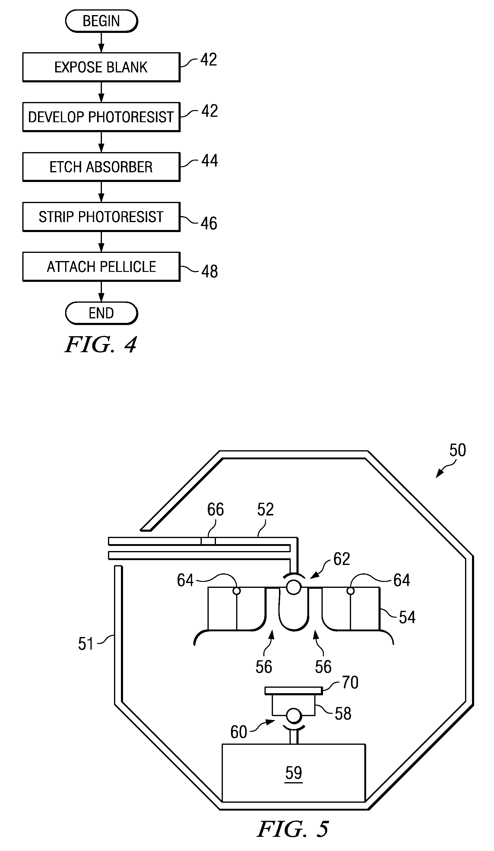
[0020]FIG. 1 illustrates a cross-sectional view of photomask assembly 10. Photomask assembly 10 includes photomask 12 coupled to pellicle assembly 14. Substrate 16 and patterned layer 18 form photomask 12, otherwise known as a mask or reticle, that may have a variety of sizes and shapes, including but not limited to round, rectangular, or square. Photomask 12 may also be any variety of photomask types, including, but not limited to, a one-time master, a five-inch reticle, a six-inch reticle, a nine-inch reticle or any other appropriately sized reticle that may be used to project an image of a circuit pattern onto a semiconductor wafer. Photomask 12 may further be a binary mask, a phase shift mask (PSM), an optical proximity correction (OPC) mask or any other type of mask suitable for use...


PUM

PropertyMeasurementUnit
flow rateaaaaaaaaaa
distanceaaaaaaaaaa
distanceaaaaaaaaaa

Abstract

A system and method for performing high flow rate dispensation of a chemical onto a photolithographic component are disclosed. The system and method includes providing a photolithographic component in a manufacturing tool. The photolithographic is positioned at a predetermined distance from a nozzle dispensing a chemical. Dispensation of a chemical at a high flow rate onto a photolithographic component, the rate of flow operable to reduce harmful effects from occurring on the surface of the photolithographic substrate.

Description

CROSS-REFERENCE TO RELATED APPLICATIONS[0001]This application is a U.S. national stage application of International Application No. PCT / US2007 / 073881 filed Jul. 19, 2007, which designates the United States of America, and claims the benefit of U.S. Provisional Application No. 60 / 807,903 filed on Jul. 20, 2006, the contents of which are incorporated herein by reference in their entirety.TECHNICAL FIELD[0002]This disclosure relates in general to semiconductor manufacturing and, more particularly, to a system and method for high flow rate dispensation of a chemical onto a photolithographic componentBACKGROUND OF THE DISCLOSURE[0003]Photolithographic components are integral to the design and fabrication of integrated circuits (ICs), liquid crystal displays (LCDs), flat panel displays, color filters, compact disks, digital video disks (DVDs), and numerous other electronic devices (as used herein, the phrase “electronic devices” means ICs, color filters, LCDs, flat panel displays, compact...

Claims


Application Information

Patent Timeline
Patent Type & Authority Applications(United States)
IPC IPC(8): B44C1/22G03F7/26
CPCG03F1/14G03F7/3021H01L21/67253H01L21/6708H01L21/6715H01L21/67051G03F1/00
Inventor COURBOIN, DANIELCHOI, JONG WOO
Owner TOPPAN PHOTOMASKS INC
Learn More