Dynamic hard magnet thickness adjustment for reduced variation in free layer stabilization field in a magnetoresistive sensor

Inactive Publication Date: 2009-07-02
WESTERN DIGITAL TECH INC
View PDF21 Cites 9 Cited by
  • Summary
  • Abstract
  • Description
  • Claims
  • Application Information

AI Technical Summary

Benefits of technology

[0008]The present invention advantageously allows a sensor manufacturer to compensate for these variations in insulation layer thickness, thereby dynamically adjusting the magnetic stabilization to a desired strength. During fabrication, the actual thickness of the insulation layer is measured. Then, one of three actions can be utilized. Action one, a determination is made as to what stripe height is necessary to achieve the desired free layer stabilization in a sensor having the measured insulation layer thickness. The location of the target air bearing surface plane is then determined based on this determined stripe height. A lapping o

Problems solved by technology

The thicker the insulation layers, the weaker the magnetic stabilization will be.
Variations and deviations in m

Method used


Image

  • Dynamic hard magnet thickness adjustment for reduced variation in free layer stabilization field in a magnetoresistive sensor
  • Dynamic hard magnet thickness adjustment for reduced variation in free layer stabilization field in a magnetoresistive sensor
  • Dynamic hard magnet thickness adjustment for reduced variation in free layer stabilization field in a magnetoresistive sensor

Examples


Embodiment Construction

[0018]The following describes various embodiments presently contemplated for carrying out this invention. This description is made for the purpose of illustrating the general principles of this invention and is not meant to limit the inventive concepts claimed herein.

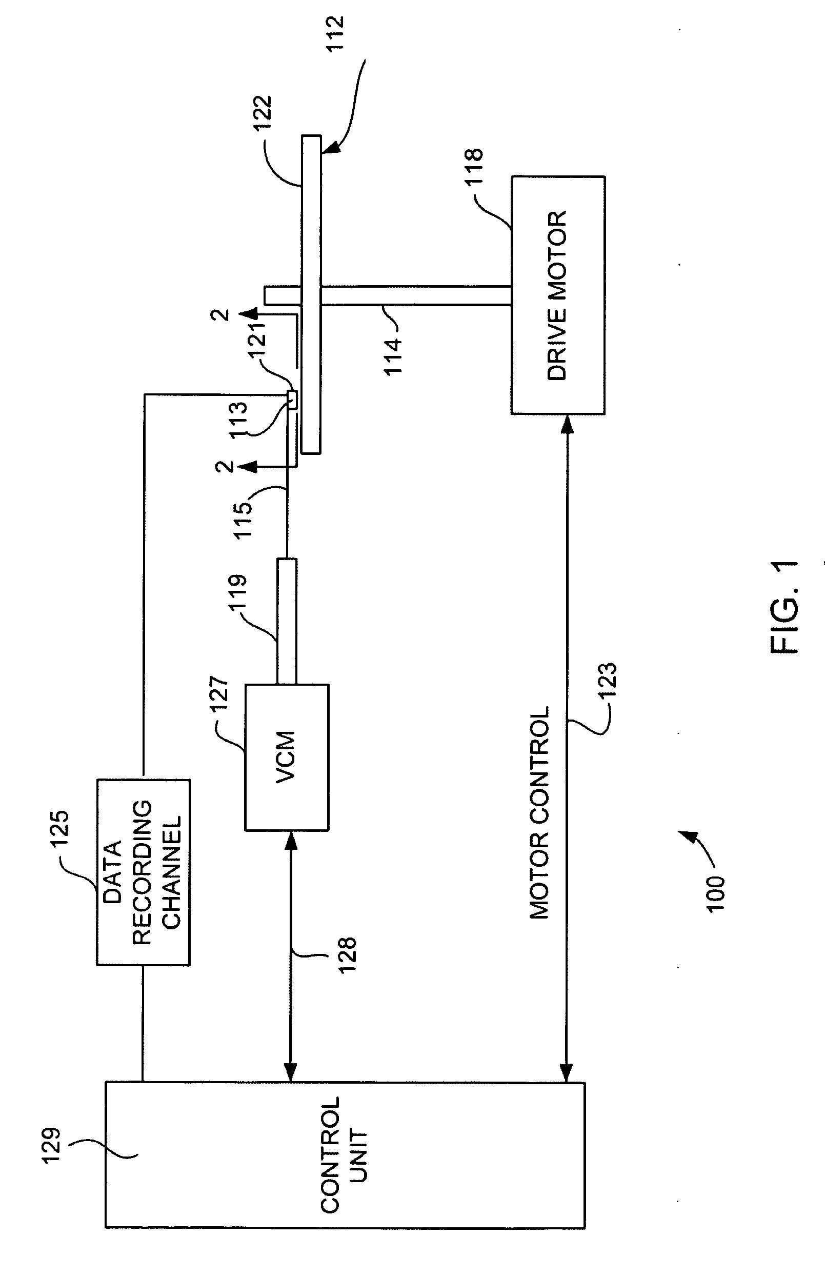
[0019]Referring now to FIG. 1, there is shown a disk drive 100 embodying this invention. As shown in FIG. 1, at least one rotatable magnetic disk 112 is supported on a spindle 114 and rotated by a disk drive motor 118. The magnetic recording on each disk is in the form of annular patterns of concentric data tracks (not shown) on the magnetic disk 112.

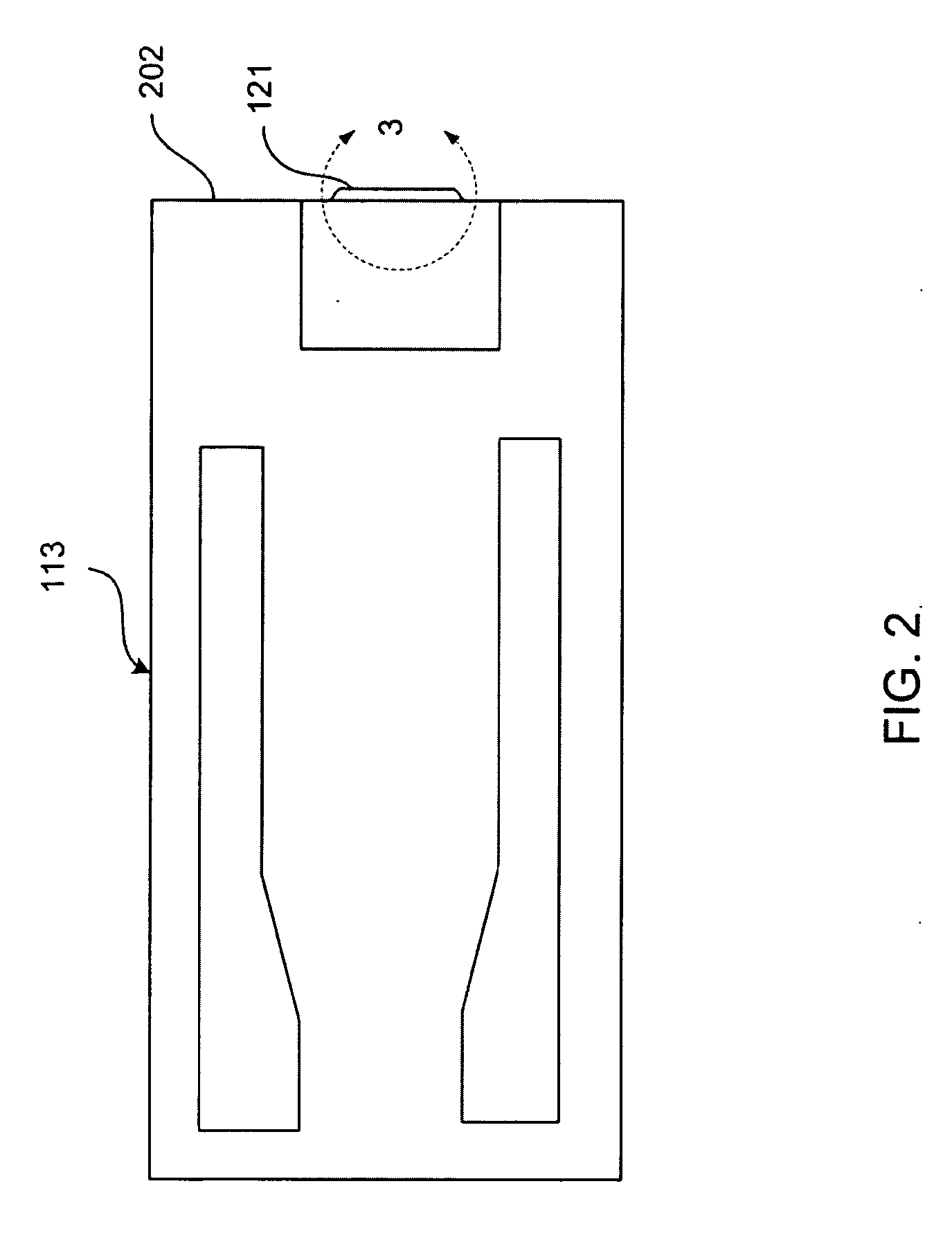
[0020]At least one slider 113 is positioned near the magnetic disk 112, each slider 113 supporting one or more magnetic head assemblies 121. As the magnetic disk rotates, slider 113 moves radially in and out over the disk surface 122 so that the magnetic head assembly 121 may access different tracks of the magnetic disk where desired data are written. Each slider 113 is att...


PUM

PropertyMeasurementUnit
Thicknessaaaaaaaaaa
Heightaaaaaaaaaa
Strengthaaaaaaaaaa

Abstract

A method for manufacturing a current perpendicular to plane magnetoresistive sensor that allows for dynamic adjustment of free layer biasing to compensate for variations in thickness of an electrically insulating layer that separates the hard bias layers from the free layer. During fabrication of the sensor, the actual thickness of the insulation layers is measured. Then, to maintain a desired magnetic stabilization of the free layer one of three options can be utilized. Option one; adjust the stripe height target to maintain the desired magnetic stabilization. Option two; adjust the hard magnet thickness to maintain the desired magnetic stabilization. Option three; use a combination of option one and option two, adjusting both the stripe height target and the hard magnet thickness to maintain the desired magnetic stabilization.

Description

FIELD OF THE INVENTION[0001]This invention relates to the construction of current perpendicular to plane magnetoresisitve sensors and more particularly to a method for controlling a free layer stabilization field in a current perpendicular to plane magnetoresisive sensor.BACKGROUND OF THE INVENTION[0002]The heart of a computer's long-term memory is an assembly that is referred to as a magnetic disk drive. The magnetic disk drive includes a rotating magnetic disk, write and read heads that are suspended by a suspension arm adjacent to a surface of the rotating magnetic disk and an actuator that swings the suspension arm to place the read and write heads over selected circular tracks on the rotating disk. The read and write heads are directly located on a slider that has an air-bearing surface (ABS). The suspension arm biases the slider toward the surface of the disk and when the disk rotates, air adjacent to the surface of the disk moves along with the disk. The slider flies on this ...

Claims


Application Information

Patent Timeline
IPC IPC(8): B05D5/12B44C1/22
CPCB82Y10/00B82Y25/00G01R33/09G11B2005/3996G11B5/3169G11B5/3909G11B5/3932G01R33/098
Inventor MARLEY, ARLEY CLEVELAND
Owner WESTERN DIGITAL TECH INC
Why Eureka
Try Eureka