
Design Method of High Magnetic Field Superconducting Magnet

a superconducting magnet and design method technology, applied in the direction of superconducting magnets/coils, magnetic bodies, instruments, etc., can solve the problems of time and effort, failure to provide solutions, etc., and achieve high magnetic field generation, high uniformity, and structural and magnetic stability.

Inactive Publication Date: 2009-12-31
KOREA BASIC SCI INST
View PDF9 Cites 10 Cited by
  • Summary
  • Abstract
  • Description
  • Claims
  • Application Information

AI Technical Summary

Benefits of technology

[0008]It is an advantage of the present invention to provide a method for designing a superconducting magnet for having structural and magnetic stability and for generating high magnetic fields with high uniformity in a predetermined space.
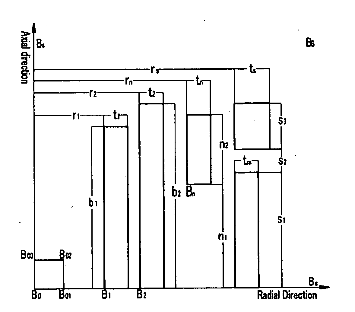
[0009]In one aspect of the present invention, a method for designing a superconducting magnet for generating high magnetic fields with high uniformity includes: a) setting volumes of a main coil and a shielding coil as variables, defining the sum of the volumes to be an objective function, and determining initial shapes of the main coil and the shielding coil and division of the main coil by using linear programming based on the objective function; and b) using non-linear programming based on the objective function, and revising the initial shapes of the main coil and the shielding coil determined in a), and determining the shape of a shimming coil.
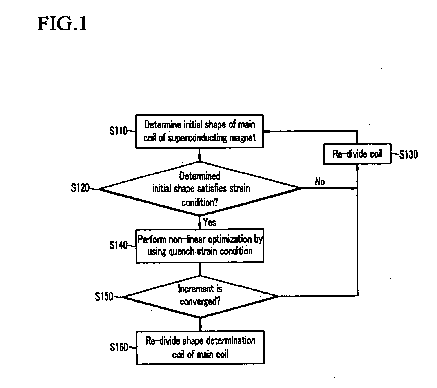
[0010]In the determination on the initial shapes of the main coil and the shielding coil using the linear programming, they are designed by using restriction conditions in which the ratio of the magnetic field in the DSV calculated by the superconducting magnet using system and the central magnetic field calculated by the shape according to the design may be less than 10−3, and in the case of shimming the main coil and the shielding coil by using non-linear programming, the design is performed by using the restriction condition in which the magnetic uniformity is given to be less than 10−5. Also, the division of the main coil for acquiring high magnetic fields is performed with the strain and the heat transfer depth as restriction conditions, and when the thickness of the divided main coil fails to satisfy the restriction condition, linear programming is performed again to re-divide the coil.
[0011]Determination of an increment for revising the shapes of the main coil and the shielding coil using non-linear programming uses restriction conditions in which the quench strain of the inner superconducting wires other than the restriction condition related to the magnetic uniformity does not exceed the critical quench strain.

Problems solved by technology

It is important for the first optimization to establish factors on the initial coil division since the first optimization initially determines division of coils and then optimizes the division, and it frequently fails to provide solutions since multi-variable optimizations cannot satisfy various given conditions.
However, the design of a superconducting magnet for acquiring high magnetic fields of more than the 9 Tesla requires division of the main coil, and the establishment of appropriate standards for dividing the coil completely depends on trial and error and designer experience.
In this instance, since plural partial minimum values can be given due to the characteristics of the multi-variable nonlinear optimization function, selection of a desired solution depends on the designer's experience, and it takes time and effort to check and estimate various results and determine an appropriate optimal solution.
Further, since the number of restriction conditions is less, a large number of partial minimum values are problematically provided, and hence it is required to establish restriction conditions that can be suitably added according to division of coils.

Method used


Image

  • Design Method of High Magnetic Field Superconducting Magnet
  • Design Method of High Magnetic Field Superconducting Magnet
  • Design Method of High Magnetic Field Superconducting Magnet

Examples


Embodiment Construction

[0015]In the following detailed description, only the preferred embodiment of the invention has been shown and described, simply by way of illustration of the best mode contemplated by the inventor(s) of carrying out the invention. As will be realized, the invention is capable of modification in various obvious respects, all without departing from the invention. Accordingly, the drawings and description are to be regarded as illustrative in nature, and not restrictive. To clarify the present invention, parts which are not described in the specification are omitted, and parts for which same descriptions are provided have the same reference numerals.

[0016]Hereinafter, a method for designing a superconducting magnet according to an embodiment of the present invention will be described with reference to drawings.

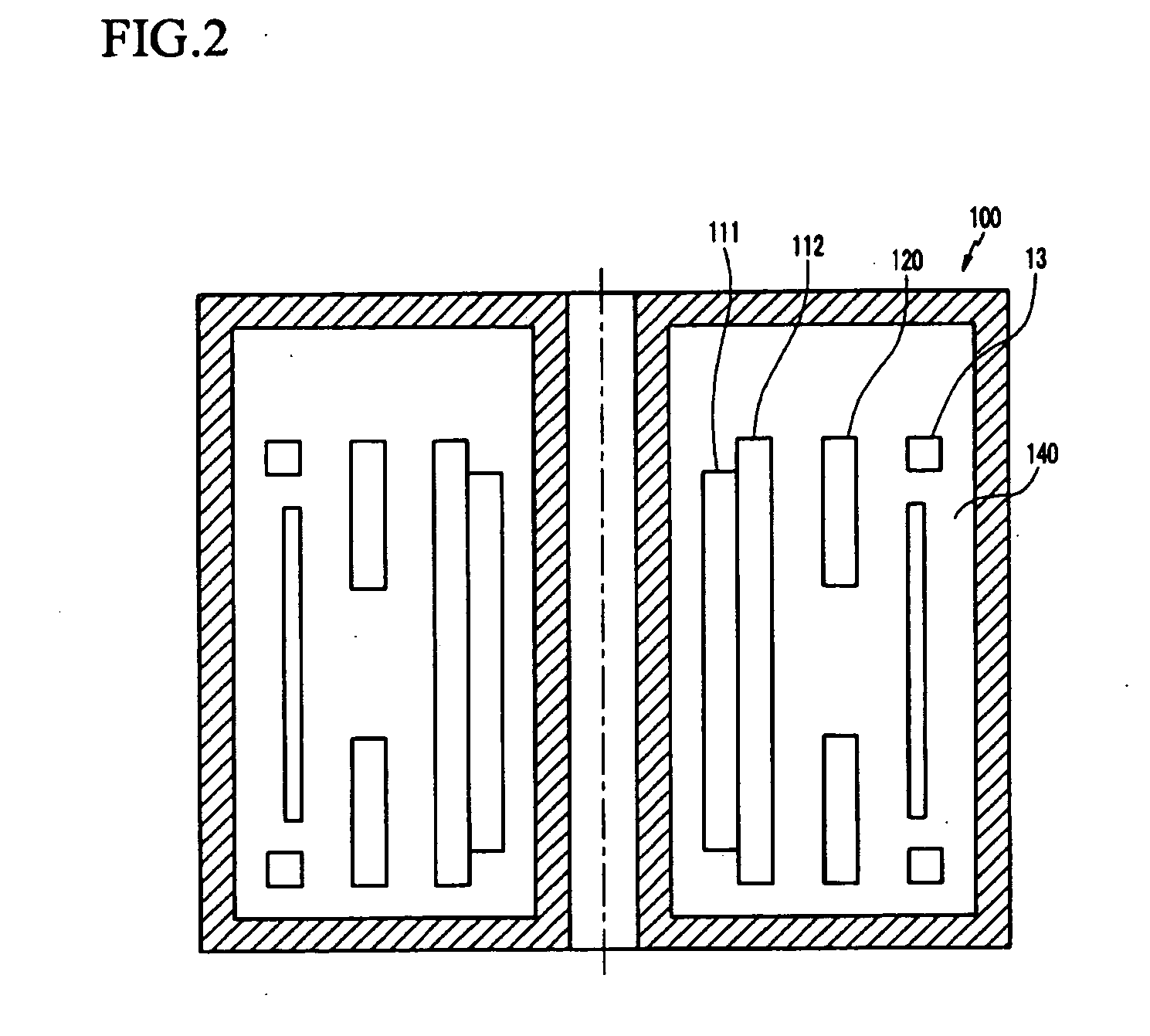
[0017]FIG. 1 shows a method for designing a superconducting magnet according to an embodiment of the present invention, and FIG. 2 shows a cross section of a main coil and a shi...


PUM


Abstract

Disclosed is a method for designing a superconducting magnet for generating high magnetic fields with high uniformity for controlling a stray field to be within an allowable range and acquiring structural and magnetic stability by optimizing the arrangement of positions and shapes of coils configuring the superconducting magnet. Volumes of a main coil and a shielding coil are set to be variables, and the critical value of a wires related on the current and magnetic field, the heat transfer depth, and the quench strain are defined to be restriction conditions so that linear programming is applied to determine an initial shape of the shielding coil and division of the main coil based on the sum of total volumes, that is, an objective function. The initial shapes of the main coil and the shielding coil determined through the linear programming are revised and the shape of a shimming coil is determined by using non-linear programming based on the objective function.

Description

BACKGROUND OF THE INVENTION[0001](a) Field of the Invention[0002]The present invention relates to a method of designing a high magnetic field superconducting magnet. More specifically, the present invention relates to the design method of superconducting magnets for generating a high magnetic field with high uniformity for acquiring structural and magnetic stability by respectively arranging positions and forms of coils configuring a superconducting magnet in an optimized method.[0003](b) Description of the Related Art[0004]A solenoid superconducting magnet is applied to systems that require high uniformity and high magnetic fields in a predetermined space such as a Fourier transform ion cyclotron resonance mass spectrometer (FT-ICR MS), a nuclear magnetic resonance (NMR) instrument, and a magnetic resonance imaging (MRI) instrument. Conventional permanent superconducting magnets for generating high magnetic fields are designed by using the multi-section solenoid scheme with magneti...

Claims


Application Information

Patent Timeline
IPC IPC(8): H01F6/06
CPCG01R33/3815H01F6/06H01F41/02
Inventor LEE, BYOUNG-SEOBKIM, DONG-LAKKIM, HYUN-SIKYOO, JONG-SHIN
Owner KOREA BASIC SCI INST
Learn More