Light emitting device

a light emitting device and side surface technology, applied in the direction of discharge tube/lamp details, luminescnet screens, lighting and heating apparatus, etc., can solve the problems of low heat radiating effect, low output of led chips, and liable to mount high output led chips, etc., to improve heat radiating effect, reduce the force required for bending the base part of the connecting part, and improve mechanical strength

Inactive Publication Date: 2009-07-02
TOYODA GOSEI CO LTD +1
View PDF19 Cites 8 Cited by
  • Summary
  • Abstract
  • Description
  • Claims
  • Application Information

AI Technical Summary

Benefits of technology

[0015]Since the side surface light emitting type light emitting device is frequently exclusively used for a light source for lighting a portable telephone, an entire size is regulated. As a result, the base body part ordinarily formed with a resin is apt to be made of a thin member. When a force required for bending the base part of the connecting part drawn out in such a base body part is increased, there is a fear that an excessive force is exerte...

Problems solved by technology

Therefore, the light emitting device is liable to mount a high output LED chip thereon.
When the temperature of the LED chip itself becomes high, the output of the LED chip is undesirably low.
However, since the s...

Method used


Image

  • Light emitting device
  • Light emitting device
  • Light emitting device

Examples


Embodiment Construction

[0022]Now, an embodiment of the present invention will be described below by referring to an illustrated example.

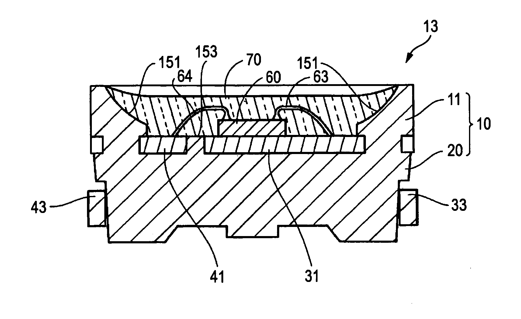
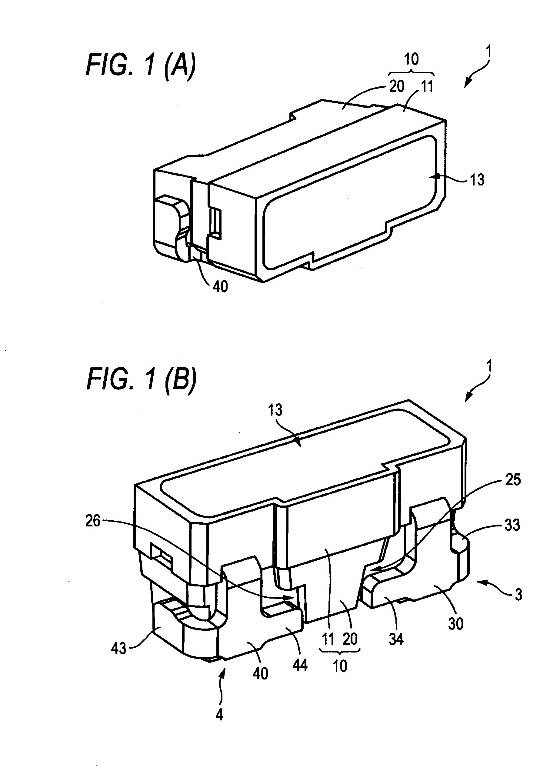
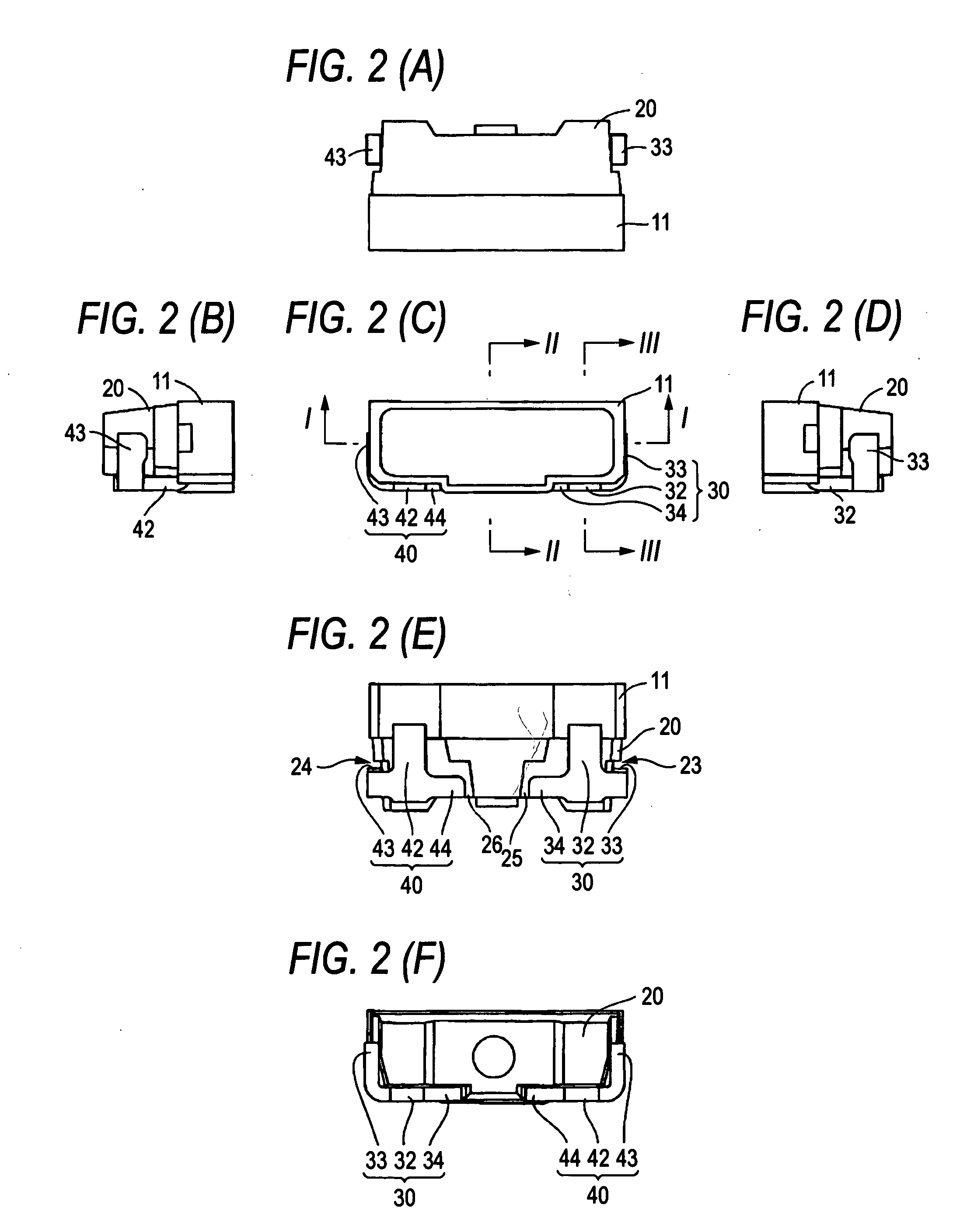
[0023]FIG. 1(A) is perspective view showing a light emitting device 1 of the embodiment from a front surface. FIG. 1(B) is a perspective view showing the light emitting device from a bottom surface. FIG. 2 is a hexahedral view. FIG. 2(A) is a plan view. FIG. 2(B) is a left side view. FIG. 2(C) is a front view. FIG. 2(D) is a right side view. FIG. 2(E) is a bottom view FIG. 2(F) is a rear view. FIG. 3 is a sectional view taken along a line I-I in FIG. 2(C). FIG. 4 is a sectional view taken along a line II-II in FIG. 2(C). FIG. 5 is a sectional view taken along a line III-III in FIG. 2(C).

[0024]As shown in FIG. 1(B), the light emitting device 1 of the embodiment includes a base body part 10, a first lead member 3 and a second lead member 4.

[0025]The base body part 10 includes a reflecting case 11 and a terminal holding part 20. As shown in FIG. 3, the reflecting case 11 has...


PUM


Abstract

In a side surface light emitting type light emitting device mounted on the surface of a wiring board, the light emitting device comprises: a base body part having a reflecting case and a terminal holding part formed integrally with the reflecting case in the rear part of the reflecting case; and lead members inserted into the base body part, having a pair of connecting parts including base parts of the connecting parts drawn out from the lower surface of the base body part and bent along the lower surface and side bending parts provided in the base parts of the connecting parts and bent along the side surfaces of the terminal holding part and connected to a pattern of the wiring board; and is characterized in that the base parts of the connecting parts are provided with protruding parts protruding toward the center of the lower surface of the terminal holding part and cut-out parts are provided for accommodating the protruding parts in the lower surface of the terminal holding part.

Description

BACKGROUND OF THE INVENTION[0001]1. Field of the Invention[0002]The present invention relates to a side surface light emitting type light emitting device mounted on the surface of a wiring board.[0003]2. Description of the Related Art[0004]An example of the light emitting device of the above-described type is disclosed in Patent Document 1. In this light emitting device, lead members are drawn out from both side parts of a reflecting case having a front part opened and a planar bottom part, and a terminal holding part is integrally provided in the rear part of the reflecting case. The parts of the lead members that are drawn out from the reflecting case are bent along the side surfaces of the terminal holding part from the side parts of the reflecting case, and further bent along the lower surface of the terminal holding part and ends thereof are accommodated in cut out parts as connecting parts.[0005]On the other hand, Patent Document 2 discloses a side surface light emitting type ...

Claims


Application Information

Patent Timeline
IPC IPC(8): H01J5/48H01L33/48H01L33/60H01L33/62H01L33/64
CPCH01L33/486H01L33/62H01L2224/48247H01L2224/48465H01L2224/48091H01L2924/00014H01L2924/00H01L2224/48257
Inventor KOKUBU, HIDEKIHAYASHI, TOSHIMASAITO, YUHKIMIYAWAKI, MICHIO
Owner TOYODA GOSEI CO LTD
Why Eureka
Try Eureka