Light source device and endoscope apparatus comprising the same

a technology of endoscope and light source, which is applied in the direction of discharge tube luminescnet screen, application, instruments, etc., can solve the problems of complicated devices and bulky devices

Active Publication Date: 2009-07-02
OLYMPUS CORP
View PDF11 Cites 80 Cited by
  • Summary
  • Abstract
  • Description
  • Claims
  • Application Information

AI Technical Summary

Benefits of technology

[0008]The present invention has been made in view of this situation, and as has its object to provide a compact light source device that can switch the projection light colors.
[0010]According to the present invention, a compact light source device that can switch the projection light colors is provided.

Problems solved by technology

This results in a bulky, complicated device.

Method used


Image

  • Light source device and endoscope apparatus comprising the same
  • Light source device and endoscope apparatus comprising the same
  • Light source device and endoscope apparatus comprising the same

Examples


first embodiment

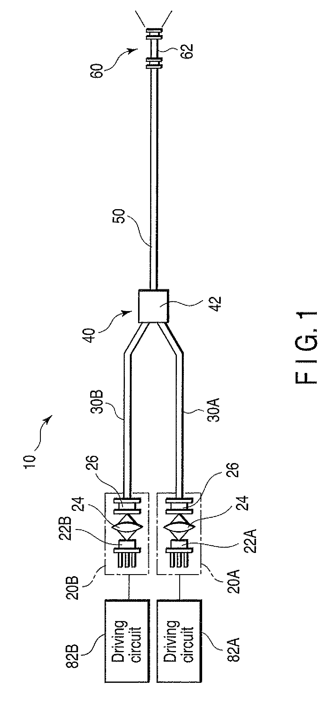
[0028]FIG. 1 shows a light source device according to the first embodiment of the present invention. As shown in FIG. 1, a light source device 10 has a first light source 20A, a second light source 20B, an optical fiber 30A to guide light projected from the first light source 20A, an optical fiber 30B to guide light projected from the second light source 20B, a photocoupler 40 connected to the optical fibers 30A and 30B, an optical fiber 50 to guide light output from the photocoupler 40, and a wavelength converter 60 to emit illumination light corresponding to the light guided by the optical fiber 50.

[0029]The first light source 20A has a first semiconductor laser 22A, a lens 24 to converge divergent light emitted from the first semiconductor laser 22A, and a connecting element 26 to optically connect the light converged by the lens 24 to the optical fiber 30A. Similarly, the second light source 20B has a second semiconductor laser 22B, a lens 24 to converge divergent light emitted ...

second embodiment

[0042]A light source device according to the second embodiment will be described with reference to FIGS. 4 to 9. In the second embodiment, a description on portions that are common with their equivalents in the first embodiment will not be repeated, and portions that are different from their equivalents will mainly be made.

[0043]FIG. 4 shows a light source device according to the second embodiment. As shown in FIG. 4, when compared to the light source device 10 of the first embodiments a light source device 10A according to the second embodiment has a third light source 20C in place of the first light source 20A, an optical fiber 30C in place of the optical fiber 30A, and a phosphor unit 62A in place of the phosphor unit 62. The third light source 20C has a third semiconductor laser 22C, a lens 24 to converge divergent light emitted from the third semiconductor laser 22C, and a connecting element 26 to optically connect the light converged by the lens 24 to the optical fiber 30C. Th...

third embodiment

[0050]A light source device according to the third embodiment will be described with reference to FIG. 10. In the third embodiment, a description on portions that are common with their equivalents in the first embodiment will not be repeated, and portions that are different from their equivalents will mainly be described.

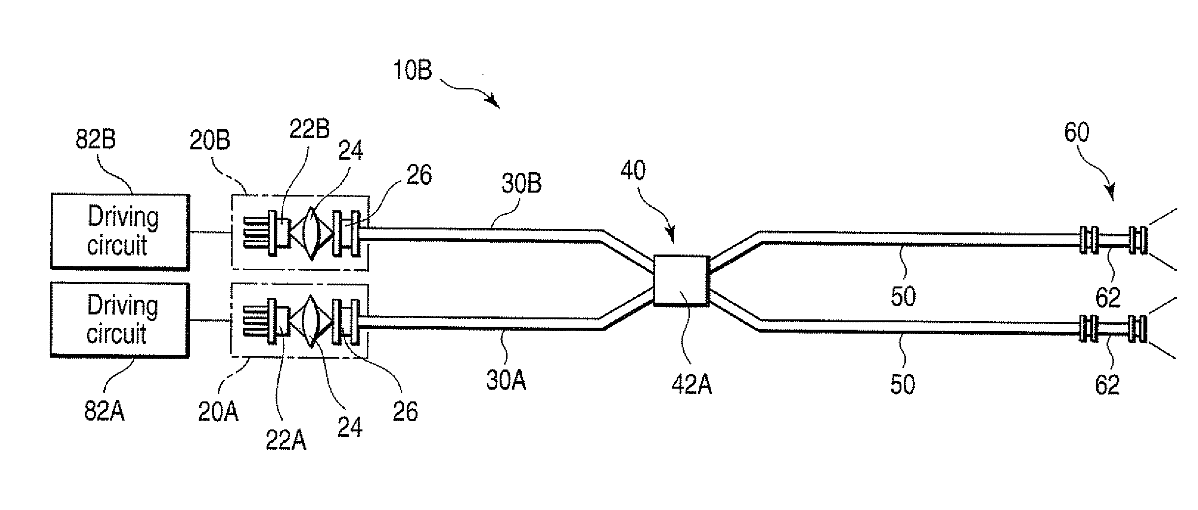
[0051]FIG. 10 shows the light source device according to the third embodiment. As shown in FIG. 10, a light source device 10B according to this embodiment comprises a two-input, two-output optical fiber coupler 42A, which has two incident ends and two exit ends. Two optical fibers 50 and two phosphor units 62 are connected to the two exit ends of the optical fiber coupler 42A. The third embodiment is different from the first embodiment in these respects.

[0052]The optical fiber coupler 42A has the two incident ends and two exit ends. The optical fiber coupler 42A distributes light entering one incident end to the two exit ends with substantially equal light intensity...


PUM


Abstract

A light source device includes a first semiconductor light source, a second semiconductor light source, and a wavelength converter. The first semiconductor light source emits light in a first wavelength range. The second semiconductor light source emits light in a second wavelength range different from the first wavelength range. The wavelength converter absorbs the light in the first wavelength range to emit light in a third wavelength range different from either of the first wavelength range and the second wavelength range, and transmits the light in the second wavelength range substantially entirely.

Description

CROSS-REFERENCE TO RELATED APPLICATIONS[0001]This application is based upon and claims the benefit of priority from prior Japanese Patent Application No. 2007-335321, filed Dec. 26, 2007, the entire contents of which are incorporated herein by reference.BACKGROUND OF THE INVENTION[0002]1. Field of the Invention[0003]The present invention relates to a light source device.[0004]2. Description of the Related Art[0005]Currently, an endoscope apparatus performs, in addition to ordinary observation using white light, a narrow band imaging, that is, an observation scheme in which the visibility of a lesion part or the like is improved using light having a specific wavelength. The endoscope apparatus having such a function is, more specifically, configured to switch between white light for ordinary observation and light having a specific wavelength for narrow band imaging, which is referred as special light hereinafter, projecting selected light from the end portion of an endoscope.[0006]Jp...

Claims


Application Information

Patent Timeline
Patent Type & Authority Applications(United States)
IPC IPC(8): H01J1/63H01J1/62
CPCA61B1/0638A61B1/0653A61B1/0661G02B6/0003G02B6/0006F21K9/56G02B6/001G02B23/2469H01S5/4025H01S5/4087A61B1/063G02B6/0008F21K9/64F21V9/30F21V9/06F21V9/08H01S5/4012H01S5/0087H01S5/02251H01S5/32341F21Y2115/30A61B1/0676A61B1/07
Inventor ITO, TAKESHI
Owner OLYMPUS CORP
Why Eureka
Try Eureka