
Thermally assisted magnetic head and manufacturing method of same

a technology of magnetic head and manufacturing method, which is applied in the field of thermally assisted magnetic head, can solve the problems of increasing the coercivity of recording media, affecting reducing the accuracy of writing, so as to achieve high precision and precise positioning

Active Publication Date: 2009-07-02
TDK CORPARATION
View PDF2 Cites 46 Cited by
  • Summary
  • Abstract
  • Description
  • Claims
  • Application Information

AI Technical Summary

Benefits of technology

The invention is about a thermally assisted magnetic head that can record high-density information on a magnetic recording medium. The head has two near-field light-generating portions that generate near-field light when laser light or other energy rays are irradiated. The main pole is positioned between the two near-field light-generating portions, and a sufficient magnetic field can be applied before the recording region cools. The head can be manufactured using a precise positioning method that allows the main pole and near-field light-generating portions to be brought close together. The invention provides a solution for high-density recording and a method for manufacturing the thermally assisted magnetic head.

Problems solved by technology

However, if the fine magnetic particles are made too small, a decline in thermal stability of magnetization, accompanying the smaller particle volume, becomes a problem.
In order to address this problem, simultaneously making KU larger is conceivable; however, this increase in KU would cause an increase in the coercivity of the recording media.
Hence if the coercivity exceeds a tolerance value determined by the limit of this write magnetic field intensity, writing is no longer possible.
This is a method of use in which in which the cooling efficiency of the medium must be made considerably poor in order to enable use; if the write speed is considered, this structure is not realistic.
Moreover, for the construction of Japanese Patent Laid-open No. 2004-158067, the magnetic field which can be applied is not adequate, and in particular, application of this head is difficult for recording media having two-stage coercivity-temperature characteristics such as described in Jan-Ulrich Thiele et al, “Magnetic and structural properties of FePt / FeRh exchange spring films for thermally assisted magnetic recording media”, IEEE Transactions on Magnetics, 2004, Vol. 40, No. 4, pp.
Using this technology, by improving the recording magnetic field gradient and similar, a magnetic field can be applied to the heating portion, but the design margin is not necessarily large, and practical realization is not easy.
When a near-field light-generating element is positioned on the substrate side from the main pole, it is preferable that the recording magnetic field be imparted from the magnetic pole after the medium is heated; however, if there is too great a distance between the two elements, the effect of heating is lost.
In Japanese Patent Laid-open No. 2006-18554, technology is disclosed in which an optical waveguide is embedded within the main pole of a perpendicular magnetic recording single-pole write head; however, it is extremely difficult to form such an optical element in a main pole of width 20 nm or less to attain a recording density of 1 Tbits / in2, and from the standpoint of efficiency of light use as well, such a design is not desirable.
As explained above, although various technologies are known, a thermally assisted magnetic head capable of performing practical high-density recording has not been obtained.
Hence when using a blue laser as the light source in high-density optical recording, for example, a core and cladding thickness of approximately 400 nm or greater each are required; in this case, the near-field light-generating portion and the main pole are greatly separated, and there is the problem that a magnetic field cannot effectively be applied to the heated medium region.

Method used


Image

  • Thermally assisted magnetic head and manufacturing method of same
  • Thermally assisted magnetic head and manufacturing method of same
  • Thermally assisted magnetic head and manufacturing method of same

Examples


Embodiment Construction

[0056]Below, near-field light-generating elements, thermally assisted magnetic heads, head gimbal assemblies, and hard disk devices of aspects are explained. The same elements are assigned the same symbols, and redundant explanations are omitted.

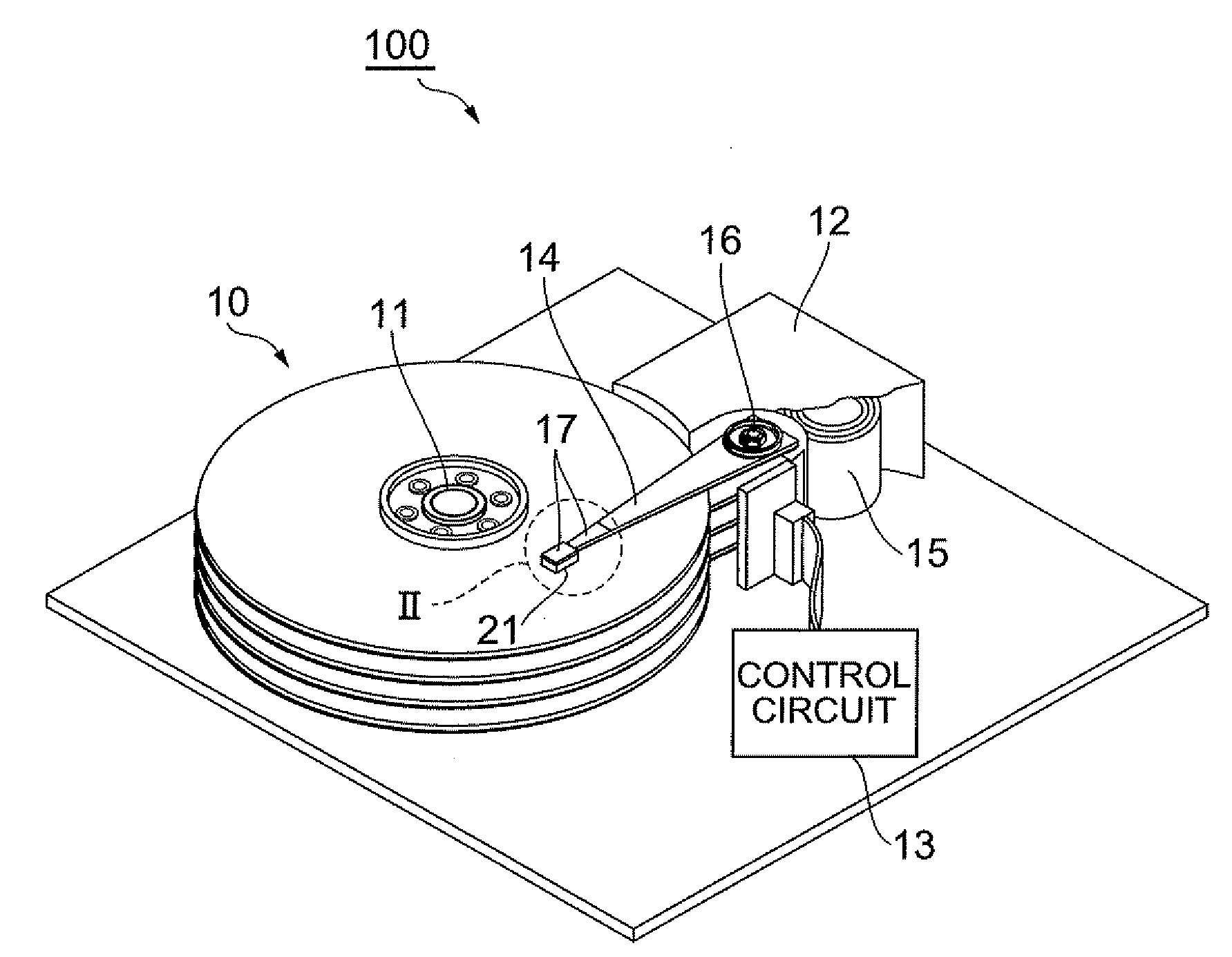
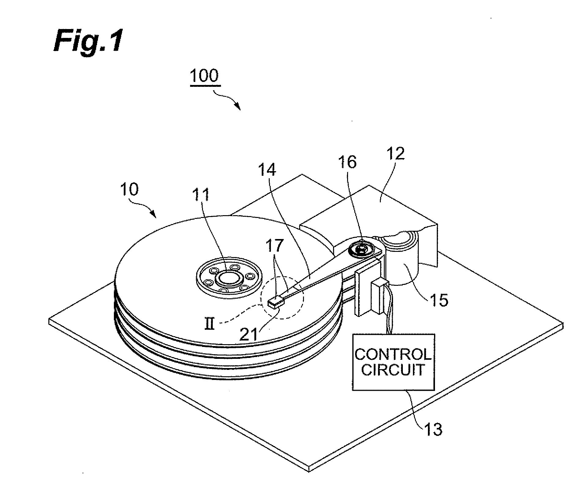
[0057]FIG. 1 is a perspective view of a hard disk device of an aspect.

[0058]The hard disk device 100 comprises magnetic disks 10, which are a plurality of magnetic recording media which rotate about the rotation shaft of a spindle motor 11; an assembly carriage device 12, to position a thermally assisted magnetic head 21 above a track; and a read / write and light emission control circuit (control circuit) 13, to control write and read operations by this thermally assisted magnetic head 21, and to control a laser diode which is the light source generating laser light for thermally assisted magnetic recording, described in detail below.

[0059]A plurality of driving arms 14 are provided in the assembly carriage device 12. These driving arms 14 ca...


PUM

PropertyMeasurementUnit
thicknessaaaaaaaaaa
magnetic fluxaaaaaaaaaa
densityaaaaaaaaaa

Abstract

When first and second near-field light-generating portions are irradiated with laser light or other energy rays, near-field light is generated at the tips of both the near-field light-generating portions. By means of the near-field light thus generated, a magnetic recording medium opposing the medium-opposing surface is heated, and the coercivity of the magnetic recording medium is lowered. Since at least a portion of the main magnetic pole is positioned within the spot region including the region between the first and second near-field light-generating portions, the tips of both the near-field light-generating portions and the main magnetic pole can be brought extremely close together, and high-density recording can be performed.

Description

BACKGROUND OF THE INVENTION[0001]1. Field of the Invention[0002]This invention relates to a thermally assisted magnetic head capable of high-density recording, and to a manufacturing method for such a head.[0003]2. Related Background Art[0004]The rising recording densities of hard disk devices have led to demands for further improved performance of thin film magnetic heads. As thin film magnetic heads, composite thin film magnetic heads, having a structure in which a magnetoresistance (MR) effect element or other magnetic detection element is laminated with an electromagnetic coil element or other magnetic recording element, are widely used; by means of these elements, data signals can be read from and written to the magnetic disks that are the magnetic recording media.[0005]In general, magnetic recording media are discontinuous media resulting from aggregation of so-called fine magnetic particles, which each of the fine magnetic particles having a single-domain structure. Here, one...

Claims


Application Information

Patent Timeline
Patent Type & Authority Applications(United States)
IPC IPC(8): G11B5/02B44C1/22
CPCG11B2005/0021G11B5/314
Inventor KOMURA, EIJISHIMAZAWA, KOJITANAKA, KOSUKETAKAYAMA, SEIICHIHATATE, HITOSHI
Owner TDK CORPARATION
Learn More