Device for stiffening the stator of a turbomachine and application to aircraft engines

a stator and turbomachine technology, applied in the field of turbomachines, can solve the problems of a turbomachine blade with a lesser stiffness and a greater axial space requirement in space, and achieve the effect of reducing the stiffness of the blade in all directions and increasing the axial space requirement of the turbomachine blad

Inactive Publication Date: 2009-07-02
TECHSPACE AERO
View PDF3 Cites 7 Cited by
  • Summary
  • Abstract
  • Description
  • Claims
  • Application Information

AI Technical Summary

Benefits of technology

[0008]To do this, an object of the invention is a turbomachine comprising a stator, a rotor arranged internally to the stator, the stator comprising at least one internal ferrule, at least one external ferrule and at least one stage of a plurality X of fixed blades each arranged between the internal and external ferrules, the stator also comprising a plurality P (P<X) of profiled members forming stiffen

Problems solved by technology

The use of more lightweight materials (composite materials non-exhaustively) also leads to much lower stiffnesses for the blades in al

Method used


Image

  • Device for stiffening the stator of a turbomachine and application to aircraft engines
  • Device for stiffening the stator of a turbomachine and application to aircraft engines
  • Device for stiffening the stator of a turbomachine and application to aircraft engines

Examples


Embodiment Construction

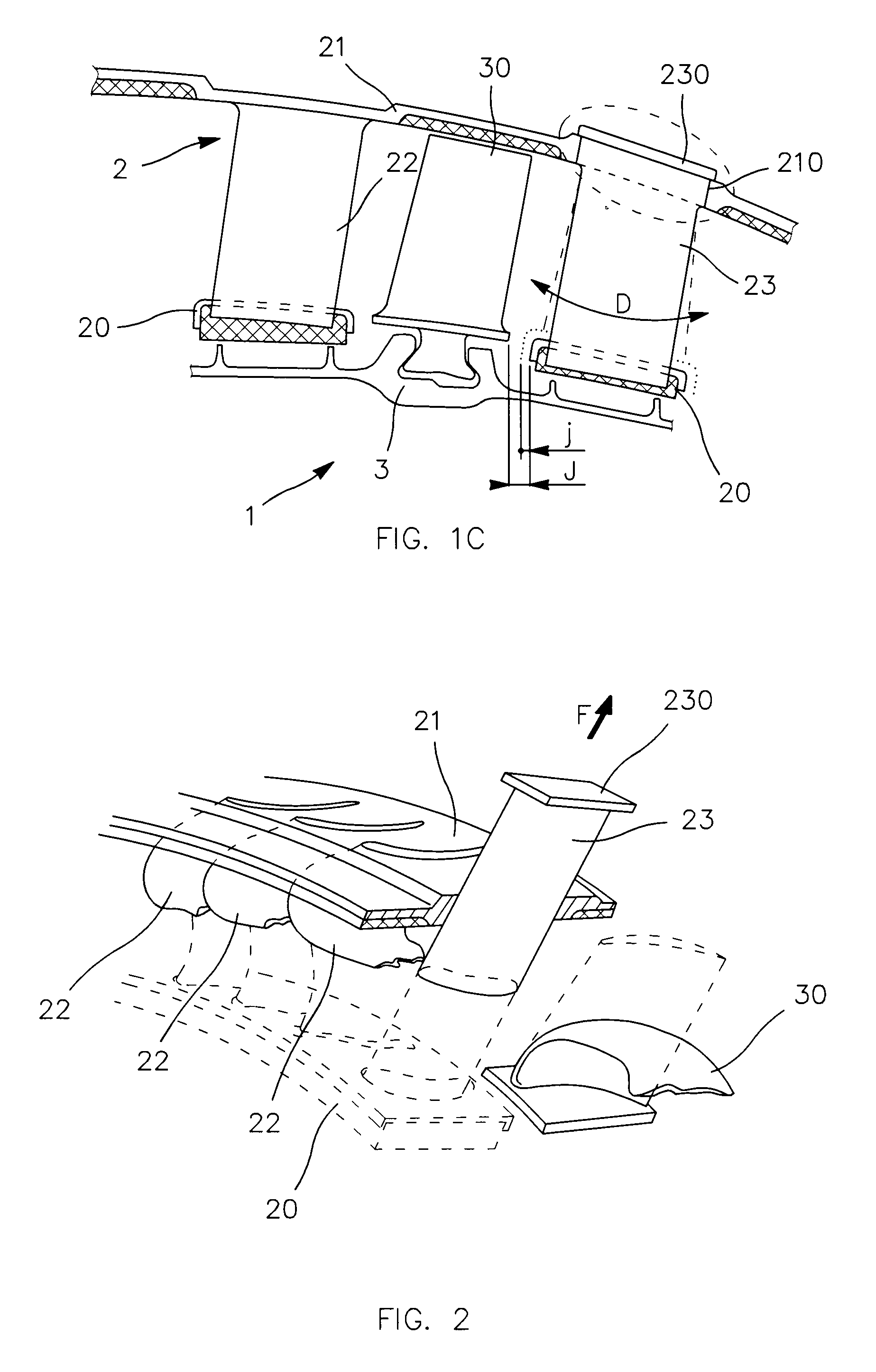
[0030]The aircraft engine according to the invention 1 comprises a stator 2, and a rotor 3 arranged internally to the stator.

[0031]In the embodiment illustrated, the rotor 3 comprises a rotary blade stage 30.

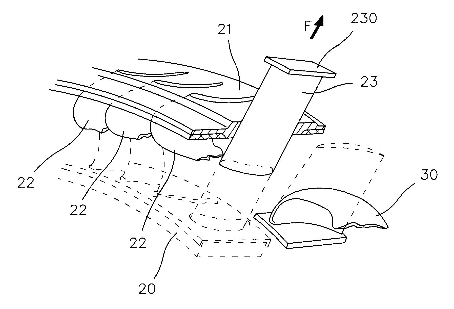
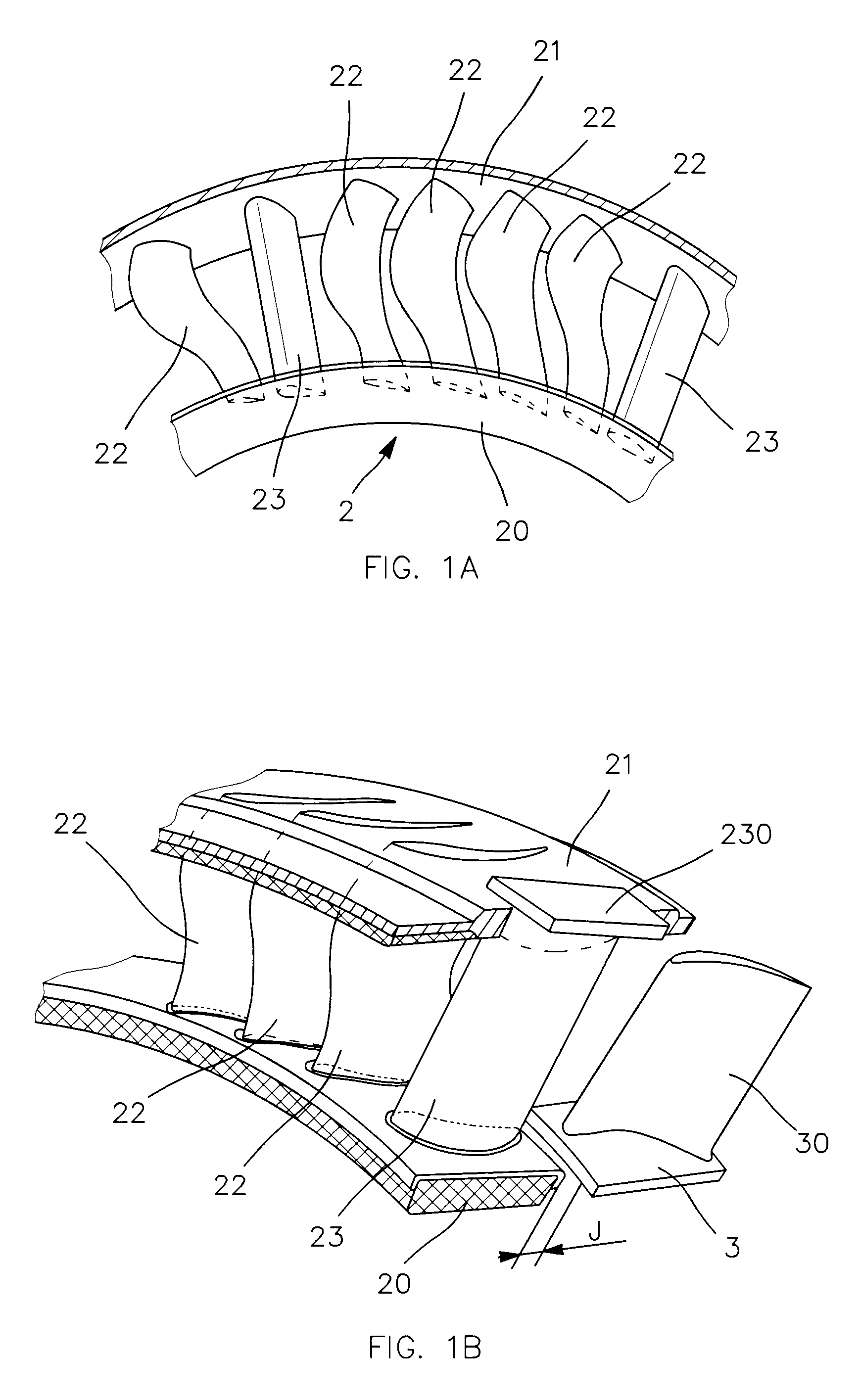
[0032]The stator 2 shown comprises several internal ferrules 20 and only one single-piece external ferrule 21. It also comprises, for each internal ferrule 20, a stage of a plurality X of fixed blades 22 each arranged between one of the internal ferrules 20 and the single-piece external one 21.

[0033]In the embodiment illustrated, the stator 2 also comprises a plurality P (P23 forming stiffeners arranged on the blade stage while being distributed uniformly at its periphery and individually between two consecutive blades 22. For example, on the angular portion of the stator shown in FIG. 1A, the stiffeners 23 are P=2 in number while being identical to each other and the blades 22 are X=5 in number while being identical to one another.

[0034]As shown, the stiffeners are fixed to the...


PUM


Abstract

The invention concerns a novel type of turbomachine.
According to the invention, the stator of the turbomachine comprises a plurality P of profiled members forming stiffeners arranged on the blade stage while being distributed uniformly at its periphery and individually between two consecutive blades, the stiffeners being fixed to the internal and external ferrules of the stator in order to uniformly increase the axial and radial stiffness of the stator in normal operation of the turbomachine and to allow to the internal ferrules to have.
The invention makes it possible to reduce the axial sizing of the turbomachine, and consequently its mass.
Application to aircraft engines, such as jet engines.

Description

TECHNICAL FIELD AND PRIOR ART[0001]The invention concerns the field of turbomachines and in particular those constituting aircraft engines, such as jet engines.[0002]At the present time, developments in aerodynamic calculation codes allowing three-dimensional calculations lead to the definition of very thin turbomachine blade profiles with consequently much lower stiffnesses in all directions in space. The use of more lightweight materials (composite materials non-exhaustively) also leads to much lower stiffnesses for the blades in all directions in space. Under nominal and especially exceptional operating conditions of the turbomachine, such as surge and stall phenomena, these reductions in rigidity are such that, under the effect of the aerodynamic pressure of the flows over the blades, significant axial movements occur at the blade root.[0003]Thus the predefined axial clearance between the stator roots and those of the rotor is oversized so as to prevent any axial contact between...

Claims


Application Information

Patent Timeline
IPC IPC(8): F01D9/02
CPCF01D5/141F01D5/147F01D9/041F01D9/042F01D21/045Y02T50/673F04D29/542F04D29/644F05D2220/3216Y02T50/672F01D25/246F04D29/544Y02T50/60
Inventor CORTEQUISSE, JEAN-FRANCOIS GERARD JACQUES
Owner TECHSPACE AERO
Why Eureka
Try Eureka