Prosthesis loading delivery and deployment apparatus

a technology of prosthesis and loading device, which is applied in the field of stents, stentgrafts and other intraluminally implantable prostheses, can solve the problems of time-consuming and difficult procedures, and achieve the effect of improving the quality of life and reducing the risk of complications

Inactive Publication Date: 2009-07-02
BOSTON SCI SCIMED INC
View PDF11 Cites 21 Cited by
  • Summary
  • Abstract
  • Description
  • Claims
  • Application Information

AI Technical Summary

Benefits of technology

[0018]To achieve these and other objects, there is provided an apparatus for loading a radially expandable prosthesis into a prosthesis confining structure for maintaining the prosthesis in a reduced-radius state, such as a compressed state for a self-expanding stent or prosthesis or a pre-delivery or quiescent state for a balloon-expandable stent or prosthesis. The apparatus includes a prosthesis capturing device with a proximal capturing section that forms a compliant enclosure. The compliant enclosure may be open at a proximal end to allow insertion of a radially expandable prosthesis in an enlarged-radius state, such as relaxed or quiescent state for a self-expanding stent or prosthesis and an enlarged state for a balloon-expandable stent or prosthesis, into the enclosure, whereby the prosthesis is surrounded or at least partially surrounded by the enclosure, including over a distal region of the prosthesis. The capturing device may further include an elongate enclosure moving section, insertable into and movable distally along a lumen or other passage of the prosthesis confining structure to locate the enclosure, and thus also locate the radially expandable prosthesis so surrounded by the enclosure, adjacent a proximal entrance of the passage. The apparatus may further include an elongate control device having a distal end region insertable into a radially expandable prosthesis in the enlarged-radius state. The distal end region may be adapted for a releasable engagement with a radially expandable prosthesis when surrounded by the prosthesis in a reduced-radius state. When in the releasable engagement, the prosthesis may track axial movement of the control device. The enclosure moving section, with the enclosure and a radially expandable prosthesis so located and with the prosthesis surrounding the distal end region of the control device, may be movable distally to draw the enclosure and the prosthesis into the passage to cause a progressive radial compression of the enclosure and prosthesis, radially contracting the prosthesis to the reduced-radius state about the distal end region to effect the releasable engagement.

Problems solved by technology

While such a procedure counteracts the problem of creep, the procedure is, however, more difficult and time consuming.

Method used


Image

  • Prosthesis loading delivery and deployment apparatus
  • Prosthesis loading delivery and deployment apparatus
  • Prosthesis loading delivery and deployment apparatus

Examples


Embodiment Construction

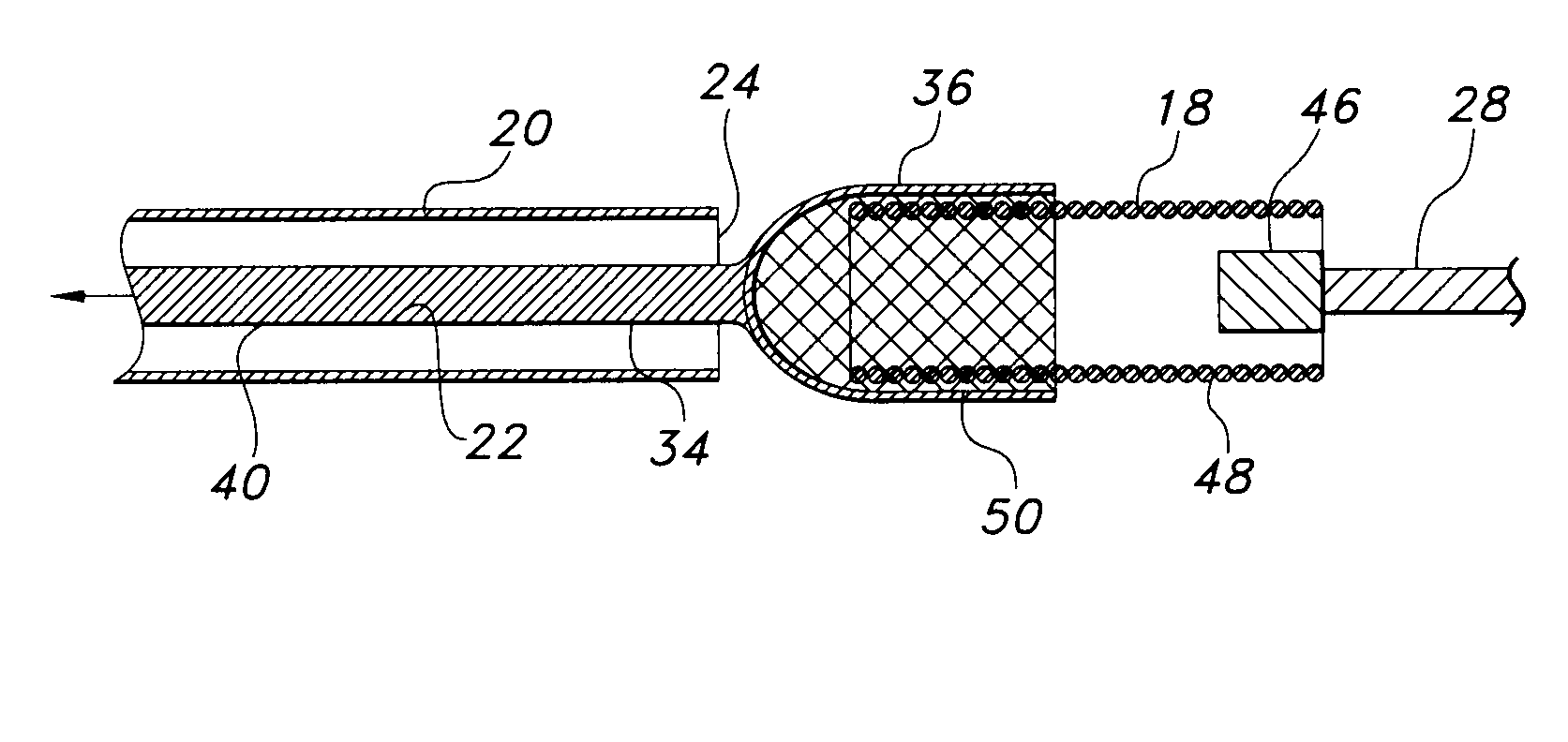
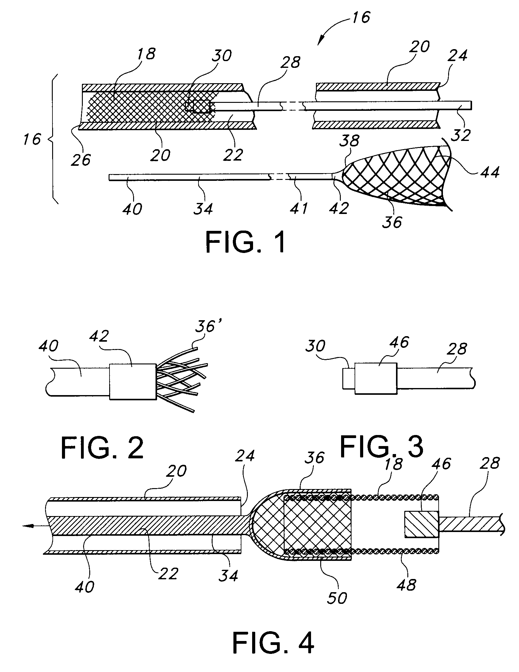
[0057]Turning now to the drawings, there is shown in FIG. 1 a stent loading and deploying system 16 for loading and deploying a radially self-expanding stent 18. While system 16 and alternative embodiment systems are discussed primarily in connection with deploying radially self-expanding stents, it can be appreciated that these systems may be used to deploy other implantable devices as well, e.g. balloon-expandable stents, grafts, and stent-grafts. As used herein, the use of the term stent may refer to and / or comprise any implantable prosthesis for use in a body lumen.

[0058]System 16 employs several components, some of which are involved in loading stent 18 and others are involved in stent deployment. The later components include an elongate, pliable outer catheter or tubing 20 constructed of a biocompatible polymer. Suitable polymers include, but are not limited to, polytetrafluoroethylene (PTFE), polypropylene (PP), or polyethylene terephthalate (PET). A central lumen 22 runs axi...


PUM


Abstract

Prosthesis loading and deploying systems include a capturing device with a proximal stent-engaging member and an elongate pulling member extending distally from the stent-engaging member. With a prosthesis or stent in a relaxed or enlarged-radius state, the pulling member is guided distally through a delivery catheter, pulling the stent-engaging member and prosthesis into the catheter lumen to progressively radially compress the prosthesis to a reduced-radius state. Simultaneously the distal end region of an elongate control device is maintained within a proximal region of the prosthesis, so that the prosthesis is compressed about the control device distal end region as these components enter the catheter. When the prosthesis is compressed about the control device, it tends to follow axial movement of the control device, thus to afford reliable positional control of the prosthesis inside the catheter by manipulating the control device.

Description

CROSS-REFERENCE TO RELATED APPLICATIONS[0001]This application claims the benefit of U.S. Provisional Application No. 61 / 017,184, filed Dec. 28, 2007, the content of which is incorporated herein by reference.FIELD OF THE INVENTION[0002]The present invention relates to stents, stent-grafts and other intraluminally implantable prostheses, and more particularly to apparatus and methods for loading prostheses into delivery catheters and other prosthesis-confining structures.BACKGROUND OF THE INVENTION[0003]A variety of treatment and diagnostic procedures involve devices intraluminally disposed within the body of the patient. Among these devices are stents, including braided stents as disclosed in U.S. Pat. No. 4,655,771 to Wallsten. The Wallsten prostheses or stents are tubular, braided structures formed of helically wound filaments. These stents typically are deployed in a reduced radius state using a delivery catheter including an outer tube. When the stent is positioned at the intende...

Claims


Application Information

Patent Timeline
Patent Type & Authority Applications(United States)
IPC IPC(8): A61F2/06A61B19/00
CPCA61F2002/9522A61F2/95A61F2/9522
Inventor RUSK, EMILYSHANK, PETERABI-KHEIRS, MICHAEL
Owner BOSTON SCI SCIMED INC
Why Eureka
Try Eureka