Inductively coupled plasma processing apparatus having internal linear antenna for large are processing

a plasma processing and linear antenna technology, applied in electrical apparatus, basic electric elements, electric discharge tubes, etc., can solve the problems of increasing the chamber, increasing the manufacturing cost, and increasing the length of the antenna source correspondingly

Active Publication Date: 2009-07-09
SUNGKYUNKWAN UNIVERSITY
View PDF11 Cites 30 Cited by
  • Summary
  • Abstract
  • Description
  • Claims
  • Application Information

AI Technical Summary

Benefits of technology

[0007]The present invention has been made to solve the above problems of the conventional ICP processing apparatus, therefore, it is a feature of the present invention to provide an ICP processing apparatus having internal linear antenna, which can be applied to a chamber having a large area and can prevent a standing wave effect, which is a sort of an interference phenomenon caused when a total length of a source matches with a half wavelength value of an RF power such as 13.56 MHz. In this case, a traveling wave is interfered with a reflecting wave, so the wave seems to be stopped without moving any directions.

Problems solved by technology

However, the spiral type antenna source causes problems as the size of the ICP chamber is enlarged.
Firstly, size and thickness of dielectric material, which maintains the vacuum state between the antenna source and the ICP chamber, are increased as the ICP chamber is enlarged, thereby increasing the manufacturing cost.
Moreover, a length of the antenna source is correspondingly increased as the ICP chamber is enlarged, so power loss is caused due to resistance of the antenna source and an evenness of the spiral type antenna source is created.

Method used


Image

  • Inductively coupled plasma processing  apparatus having internal linear antenna for large are processing
  • Inductively coupled plasma processing  apparatus having internal linear antenna for large are processing
  • Inductively coupled plasma processing  apparatus having internal linear antenna for large are processing

Examples


Embodiment Construction

[0022]Hereinafter, example embodiments of the present invention will be described in detail with reference to accompanying drawings. The example embodiments described below will not limit the scope of the present invention, but show examples of the present invention.

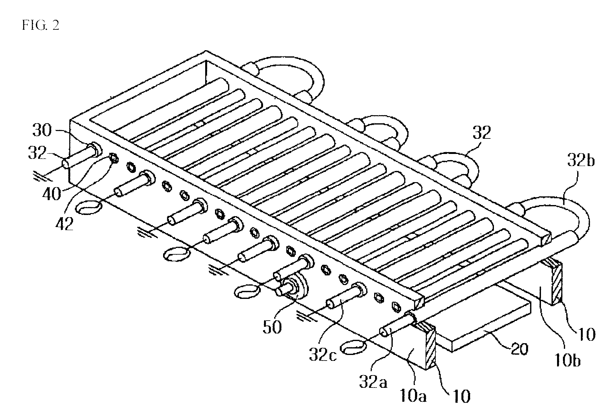
[0023]FIG. 2 is a schematic perspective view of bending type internal linear antennas according to one example embodiment of the present invention. Referring to FIG. 2, a stage 20 is installed at a lower portion of a reaction chamber 10 in order to place a substrate (not shown) thereon in such a manner that a plasma etching process or a deposition process is carried out with respect to the substrate. Preferably, the stage 20 moves up and down and can be formed as an electrostatic chuck.

[0024]An exhaust line connected to a vacuum pump (not shown) is formed at a bottom wall or at a part of a sidewall of the reaction chamber 10.

[0025]A bias power section is connected to the stage 20 in order to apply bias power to the stage...


PUM

PropertyMeasurementUnit
lengthaaaaaaaaaa
pressureaaaaaaaaaa
lengthaaaaaaaaaa

Abstract

An inductively coupled plasma processing apparatus for a large area processing includes a reaction chamber and a bending type antenna structure. The bending type antenna structure includes bending type linear antennas. Each of the bending type linear antennas has a first end, a second end and a bended portion. The bending type linear antennas are arranged horizontally in parallel with the substrate to pass through the reaction chamber inside the reaction chamber. The bending type linear antennas are spaced apart from each other. A bended portion of a bending type linear antenna is protruded out of the reaction chamber, a first end of each of the bending type linear antennas is protruded out of the reaction chamber and is coupled to an RF power, and a second end of each of the bending type linear antennas is protruded out of the reaction chamber and is coupled to a ground.

Description

[0001]This application is Continuation-in-part of Ser. No. 11 / 643,664 filed Dec. 22, 2006, which is a Divisional of application Ser. No. 10 / 438,221 filed May 15, 2003, which claims priority from Korean patent application 2003-28849 filed May 7, 2003. The entire content of the aforementioned applications are incorporated herein by reference.BACKGROUND[0002]1. Technical Field[0003]The present invention relates to an inductively coupled plasma processing apparatus, and more particularly to an inductively coupled plasma processing apparatus, in which a linear antenna creating an electric field is accommodated in a reaction chamber for carrying out a plasma etching process over a large area.[0004]2. Description of the Related Art[0005]Generally, an inductively coupled plasma (ICP) processing apparatus includes a spiral type antenna, which is installed at an upper outer portion of a reaction chamber by interposing dielectric material between the spiral type antenna and the reaction chambe...

Claims


Application Information

Patent Timeline
Patent Type & Authority Applications(United States)
IPC IPC(8): C23F1/00
CPCH01J37/321
Inventor YEOM, GEUN-YOUNGLEE, YOUNG-JOONKIM, KYONG-NAM
Owner SUNGKYUNKWAN UNIVERSITY
Why Eureka
Try Eureka