Unlock instant, AI-driven research and patent intelligence for your innovation.

Large power multi-outputs power supply structure having relatively high efficiency in load range and controlling method thereof

Active Publication Date: 2009-07-09
DELTA ELECTRONICS INC
View PDF10 Cites 10 Cited by
  • Summary
  • Abstract
  • Description
  • Claims
  • Application Information

AI Technical Summary

Benefits of technology

[0007]It is therefore an object of the present invention to provide a large power switched-mode power supply, the power supply has a relatively high efficiency in a load rang, and it employs a parallelized structure including a multi-outputs converter and a single-output converter, effectively increases the light-load efficiency of the power supply, and resolves the heat dissipation problem of the transformers and the cross regulation problem of the multi-outputs converters.

Problems solved by technology

Recently, the worldwide energy crisis is becoming even more serious.
Thus fully utilizing energy resource and decrease the energy waste becomes more and more urgent.
In the consumer electronic products, the desktop computers and the workstation computers occupy a quite large percentage, and the low efficiency of the switched-mode power supply of these products has brought a great deal of energy waste.
If the structure of FIG. 1 is employed, it will cause two problems: 1. Due to the influence of the parasitic parameters of the coupled inductor between the outputs of +12 V and +5 V, the weighted feedback of two output voltages of +12 V and +5 V will interact each other and the output voltages can't be regulated stably, this is the cross regulation problem; 2. A single transformer bearing the whole output power raises the difficulty of heat dissipation design.
Due to the different output voltages of the two transformers, the two transformers are independent from each other, and both are always working in the whole load range, thus the efficiency of the DC / DC converter stage in light load is not very high.

Method used


Image

  • Large power multi-outputs power supply structure having relatively high efficiency in load range and controlling method thereof
  • Large power multi-outputs power supply structure having relatively high efficiency in load range and controlling method thereof
  • Large power multi-outputs power supply structure having relatively high efficiency in load range and controlling method thereof

Examples


Embodiment Construction

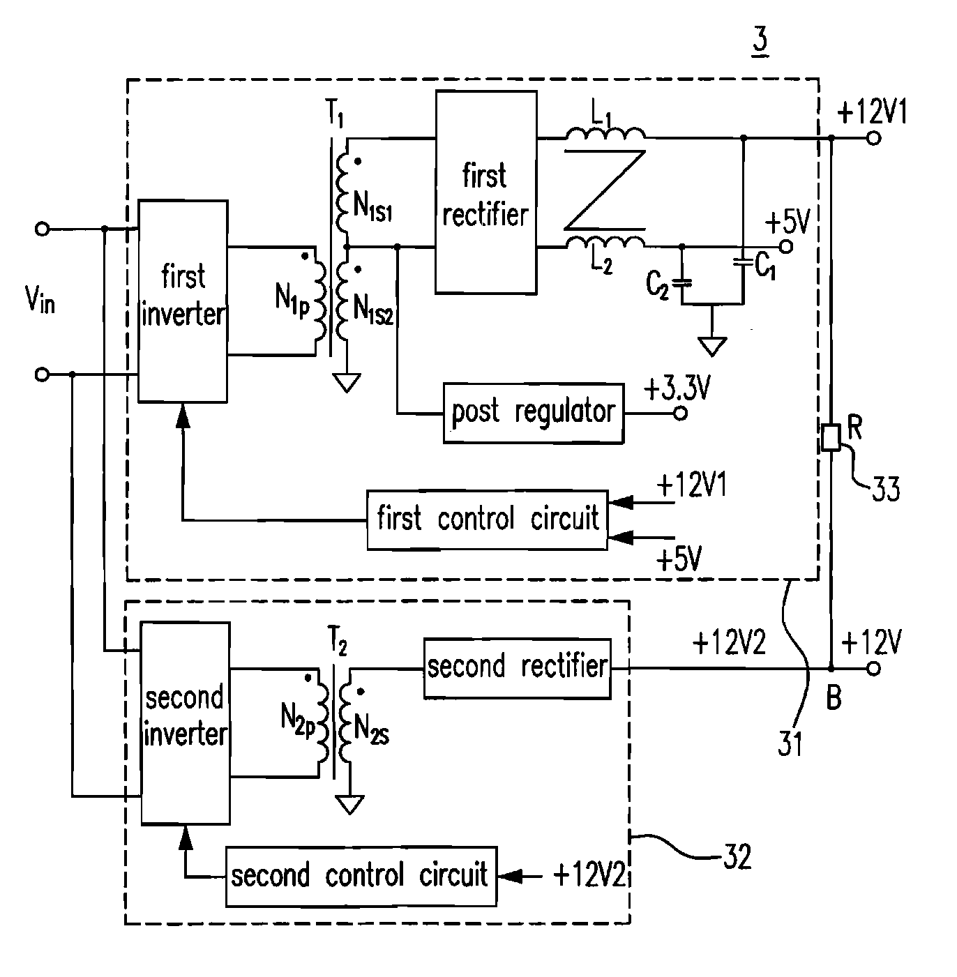
[0037]The proposed new technical solution of the present invention is focused on a switched-mode power supply of workstation computer having a large power and multi-outputs such that it could accomplish a relatively high efficiency in wide load, and the design is simplified, cost is also reduced. In the workstation computers, the ratio of output power of +12 V is quite high (usually it is around 80%). The first preferred embodiment of the present invention is shown in FIG. 3(a). A DC / DC converter stage 3 includes a multi-outputs converter 31 (it is a DC / DC converter), a single-output converter 32 (it is also a DC / DC converter) and a resistive element 33. In which, the multi-outputs converter 31 includes a first inverter, a first transformer T1 having a first primary winding N1p coupled to the first inverter, a first secondary winding N1s1 and a second secondary winding N1s2, a first rectifier coupled to the first secondary winding N1s1, a first filter (including a first inductor L1 ...


PUM


Abstract

The configurations of a switched-mode power supply and a controlling method thereof are provided. The proposed switched-mode power supply includes a first output converter receiving a DC input voltage and generating a first high power DC voltage output and at least one low power DC voltage output, and a second output converter receiving the DC input voltage and generating a second high power DC voltage output coupled to the first high power DC voltage output to generate a coupled output, wherein the first output converter works and the second output converter idles when a transient power of the coupled output is not larger than a rated output power of the first high power DC voltage output, and both the first and the second output converters work when the transient power is larger than the rated output power.

Description

FIELD OF THE INVENTION[0001]The present invention relates to a switched-mode power supply. More particularly, the present invention relates to a power supply having a parallelized structure including a multi-outputs converter and a single-output converter with a relatively high efficiency in a wide load range and a controlling method thereof.BACKGROUND OF THE INVENTION[0002]Recently, the worldwide energy crisis is becoming even more serious. Thus fully utilizing energy resource and decrease the energy waste becomes more and more urgent. In the consumer electronic products, the desktop computers and the workstation computers occupy a quite large percentage, and the low efficiency of the switched-mode power supply of these products has brought a great deal of energy waste. For that matter, Energy Star increases the forced efficiency standard to more than 80% when switched-mode power supply for the desktop computers and the workstation computers load from 20% to 100% since Jul. 20, 200...

Claims


Application Information

Patent Timeline
IPC IPC(8): H02J1/00
CPCH02M3/33561H02M3/285
Inventor LI, FEIGAN, HONGJIANYING, JIANPING
Owner DELTA ELECTRONICS INC
Features
  • R&D
  • Intellectual Property
  • Life Sciences
  • Materials
  • Tech Scout
  • Unparalleled Data Quality
  • Higher Quality Content
  • 60% Fewer Hallucinations
Learn More