Objective-coupled selective plane illumination microscopy

a selective plane and illumination microscopy technology, applied in the field of objective-coupled selective plane illumination microscopy, can solve the problems of hazy and unfocused fluorescence, the technique is not suited to studying individual cells, and the study method encounters serious difficulties in studying the activity of entire populations of neurons or neural circuits. achieve the effect of improving the projection from the sample and rapid three-dimensional imaging

Inactive Publication Date: 2009-07-09
WASHINGTON UNIV IN SAINT LOUIS
View PDF8 Cites 38 Cited by
  • Summary
  • Abstract
  • Description
  • Claims
  • Application Information

AI Technical Summary

Benefits of technology

[0009]In one embodiment, a microscope assembly may include an illumination source coupled to an optical assembly by a coupler. The optical assembly may include an objective with optics that move along an optic axis. The illumination source may generate a light blade that illuminates a portion of a sample at an illumination plane. The light blade can induce a fluorescent emission from the sample that is projected through the objective optics to a detector. In other embodiments, the light from a laser or other source propagates through free space to the optics that create the light blade. The focal plane of the objective optics may be fixed with respect to the illumination source by the coupler so that the illumination plane is coincident with the focal plane as the objective optics move along the optic axis. In one embodiment, the coupler is a mechanical arrangement that physically connects the illumination optics to the objective, while in another embodiment the coupling is achieved by a control system that electronically insures the illumination optics maintain a fixed relationship relative to the focal plane of the objective. In one aspect, the objective and illumination may be rapidly scanned along the optic axis to provide rapid three-dimensional imaging. The microscope assembly may be tilted in some embodiments so that the illumination plane illuminates the sample at an angle, thereby improving the projection from the sample that is detected by the detector. In an embodiment, the illumination source may include fiber and a fiber optic assembly coupled to the objective. In this embodiment, the fiber carries light from a laser to the fiber optic assembly which focuses the light to a thin light blade at the focal plane.

Problems solved by technology

However, this optical method is not suited for studying individual cells in densely-labeled, three-dimensional tissues: these optical methods do not reject out-of-focus light, resulting in a hazy and unfocused fluorescence.
However, these techniques encounter serious difficulties in studying the activity of entire populations of neurons or neural circuits, largely because of their intrinsically slow rate of data collection and / or rapid photo bleaching of the sample.
This method results in several problems.
First, only small samples are effectively sectioned, because the light might otherwise have to propagate through many centimeters of tissue.
Also, because the optics and camera are placed above the sample and the sample must be moved to obtain sectioned images, a three-dimensional image can only be acquired slowly.
This can blur sample images and does not provide accurate sample images.

Method used


Image

  • Objective-coupled selective plane illumination microscopy
  • Objective-coupled selective plane illumination microscopy
  • Objective-coupled selective plane illumination microscopy

Examples


Embodiment Construction

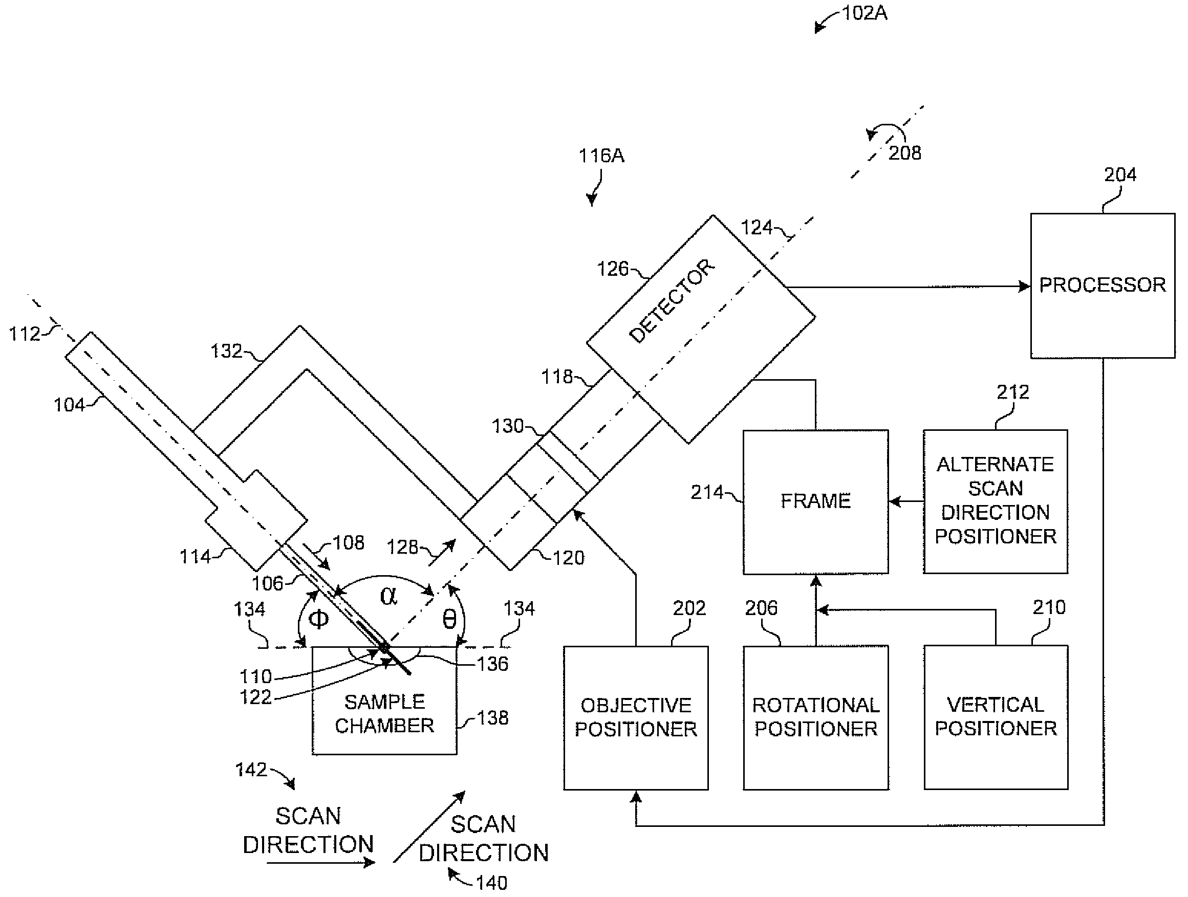
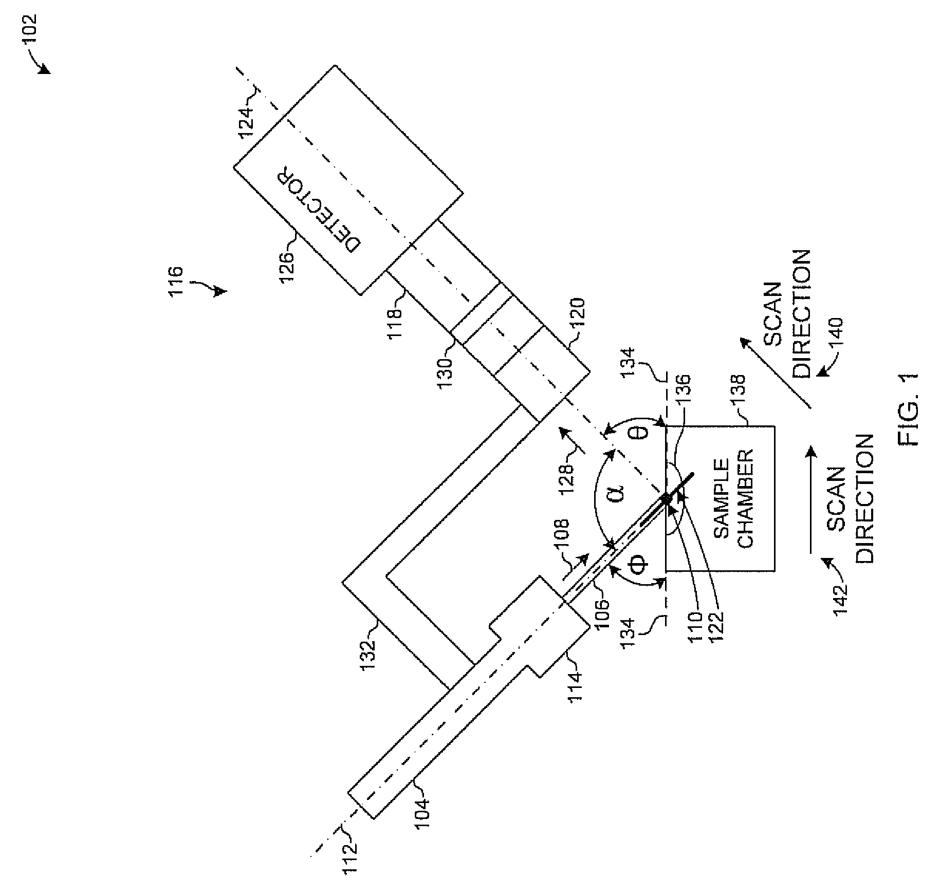
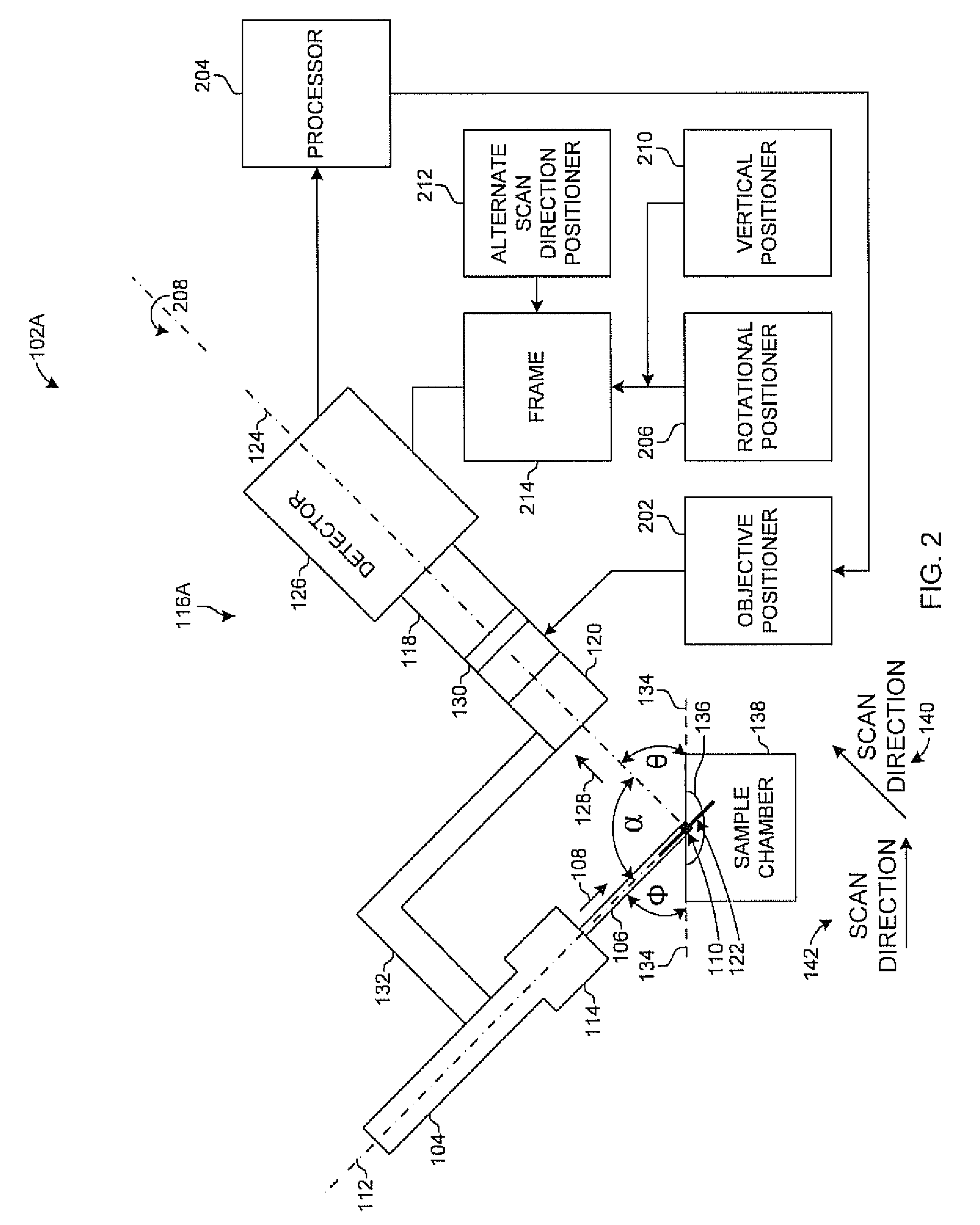
[0014]Objective-coupled planar illumination restricts the illumination of a sample to the focal plane of a microscope objective lens. Objective-coupled planar illumination therefore performs optical sectioning using a thin “blade” of light to restrict illumination near the focal plane. The light blade generally is produced using a cylindrical lens to focus light from a laser or other illumination source. In one implementation, an optical fiber carries the light from the laser to the cylindrical lens. Producing the light blade with a cylindrical lens results in weak convergence in one, but not the other, dimension of the collimated output of a fiber-coupled laser.

[0015]Because of diffraction, the light blade is not arbitrarily thin. If a sample has a constant thickness d, then the minimum width of the blade is of the order √{square root over (λd)}, where λ is the wavelength of light. In one example, a light blade's width is in the range of 5-10 micrometers (μm), which will produce ef...


PUM


Abstract

A microscope assembly (102) includes an illumination source (104) coupled to an optical assembly by a coupler (132). The optical assembly includes an objective with optics that move along an optic axis. The illumination source (104) generates a light blade (106) that illuminates a portion of a sample (136) at an illumination plane (110). The light blade (106) induces a fluorescent emission from the sample (136) that is projected through the objective optics to a detector (126). The focal plane (122) of the objective optics is fixed with respect to the illumination source (104) by the coupler (132) so that the illumination plane (110) is coincident with the focal plane (122) as the objective optics move along the optic axis (124). The objective and illumination may be rapidly scanned along the optic axis to provide rapid three-dimensional imaging while the objective and illumination may also be rapidly scanned along the optic axis (124) to provide rapid three-dimensional imaging.

Description

FEDERALLY SPONSORED RESEARCH OR DEVELOPMENT[0001]The present invention was made, at least in part, with funding from the National Institutes of Health, NIH Grant 1 R01 DC005964-01A1 (Holy). Accordingly, the United States government may have certain rights in this invention.BACKGROUND[0002]Many biological or medical phenomena are studied using optical imaging. Optical imaging, most often in the form of microscopy, can yield insights at cellular and sub-cellular levels as well as over coarser scales.[0003]Particular proteins or other cellular components can be tagged with a fluorescent dye for study by fluorescence microscopy. Alternatively, dyes that change their fluorescence depending on calcium levels, pH, membrane voltage, or other physical or chemical characteristics can be used to report on biological phenomena such as the activity of neurons.[0004]One frequent approach to studying these phenomena is to use wide-field illumination, often called epifluorescence. However, this opt...

Claims


Application Information

Patent Timeline
Patent Type & Authority Applications(United States)
IPC IPC(8): G02B21/06G02B21/02
CPCG02B21/16G02B21/08G02B21/006G02B21/008
Inventor HOLY, TIMOTHY E.HOLEKAMP, TERRENCE F.
Owner WASHINGTON UNIV IN SAINT LOUIS
Why Eureka
Try Eureka