Optical glass, glass molded body, optical device and their production methods

Active Publication Date: 2009-07-09
HOYA CORP
View PDF10 Cites 19 Cited by
  • Summary
  • Abstract
  • Description
  • Claims
  • Application Information

AI Technical Summary

Benefits of technology

[0031]According to this invention, there can be provided a high-refractivity low-dispersion optical glass excellent in devitrification resistance, a glass material for shaping by heating and softening and an optical ele

Problems solved by technology

However, a glass that satisfies the above optical properties has a large content of rare earth metal components), and the content of components) for forming a glass network is relatively decreased, so that it has a problem that it is degraded in devitrifica

Method used


Image

  • Optical glass, glass molded body, optical device and their production methods
  • Optical glass, glass molded body, optical device and their production methods
  • Optical glass, glass molded body, optical device and their production methods

Examples


example 1

[0181]Raw materials such as oxides, hydroxides, carbonates, nitrates, etc., were selected as required and weighed so as to obtain compositions shown in Tables 1 and 3. In each Example, the thus-prepared raw materials were mixed and then melted in a platinum crucible. Glasses in Examples were melted at 1,300 to 1,450° C. The glasses were stirred and refined, and then each glass was cast on an iron plate to form blocks. Each glass block was placed in a furnace that had been heated to a temperature in the vicinity of its glass transition temperature, and the blocks were annealed to room temperature. Samples for various measurements were cut out from each of the this obtained glass blocks, and measured as follows.

[0182]A sample was measured for a refractive index nd and an Abbe's number νd according to Japan Optical Glass Industry Society Standard JOGIS-01.

[0183]A sample was also measured for a coloring degree according to Japan Optical Glass Industry Society Standard JOGIS-02. Table 1 ...

example 2

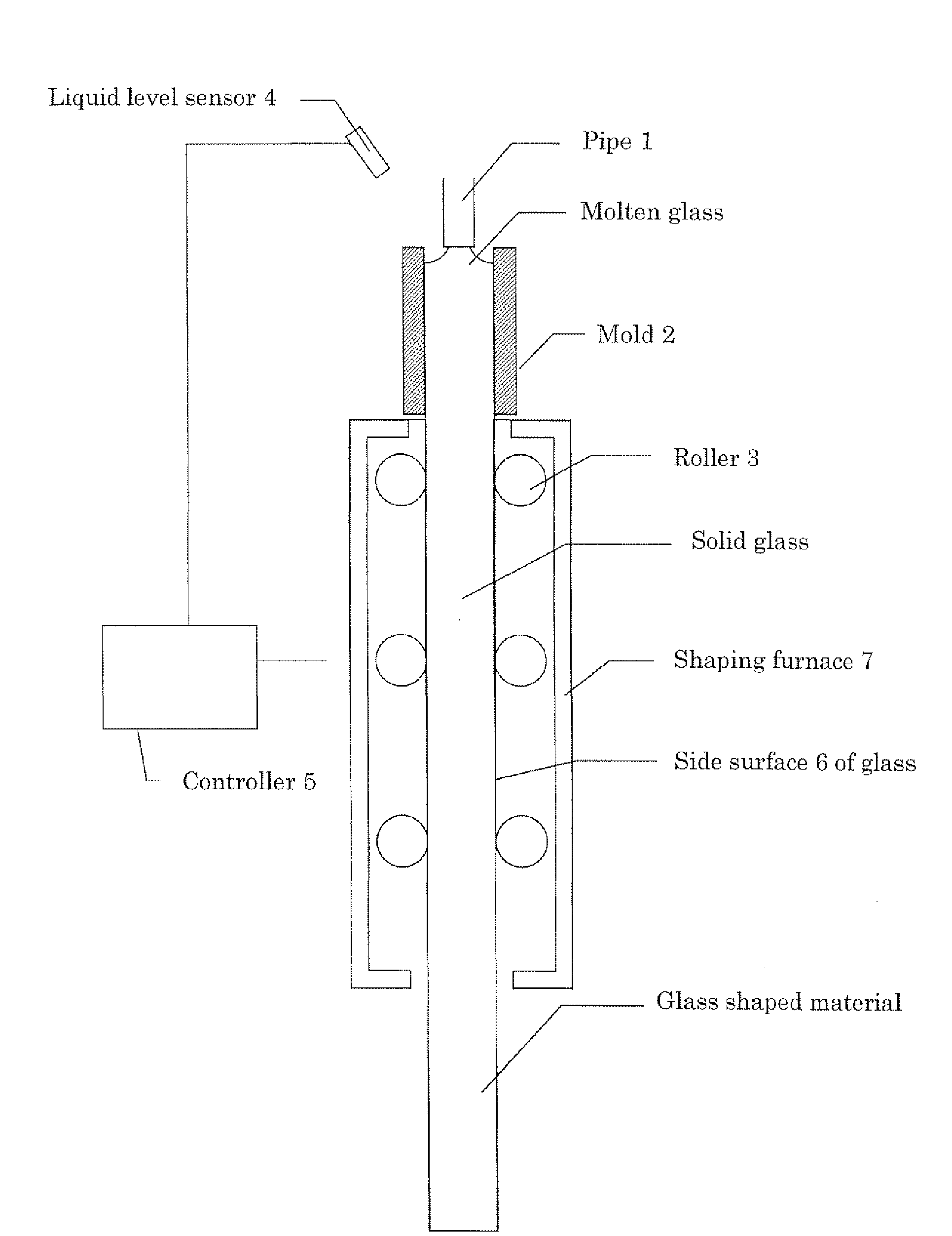
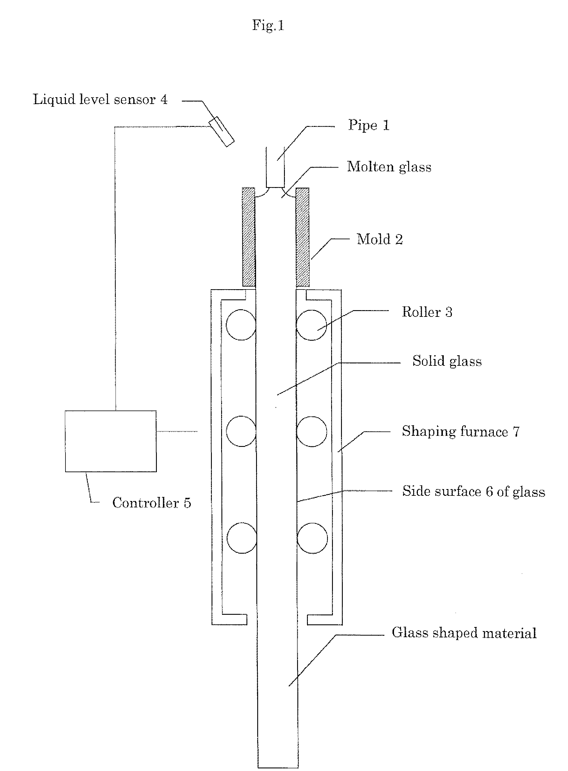
[0191]Glass raw materials were weighed so as to give the same optical glasses as those produced in Example 1, and for each glass, they were fully mixed and then introduced into a melting vessel, followed by heating and melting. Then, they were fully refined and homogenized to obtain molten glasses, and each molten glass was respectively caused to continuously flow out from the outlet of a vertically arranged pipe at a constant flow speed and caused to flow into the center of the inlet of a through hole formed in a carbon mold arranged in a position shown in FIG. 1. The through hole of the mold had an inner diameter of φ20 mm and was arranged such that the center axis of the through hole was set in the vertical direction, and the center axis of the pipe and the center axis of the above through hole were arranged to be in agreement with each other. The through hole of the mold had a length of several hundreds millimeters, and a band heater that was not shown was wrapped around the mol...

example 3

[0196]Press-molding glass materials were prepared as follows from those gradually cooled rod-shaped glasses prepared in Example 2. First, a marking line was formed on that portion of a rod-shaped glass side surface which was to be split apart? by a scribing. Then, the rod-shaped glass was inserted into a pressure vessel, and arranged such that the portion where the marking line had been formed was positioned in the center of the vessel. The rod-shaped glass was chucked at the opening portions of the vessel with rubber seals in a manner that the movement thereof in the center axis direction was not restricted, and by injecting water, the vessel was filled with water so as not to internally contain bubbles.

[0197]In this state, the water pressure in the vessel was increased to divide the rod-shaped glass perpendicular to the center axis thereof in the position of the marking line. In this manner, the rod-shaped glass was split apart at predetermined intervals to prepare cut pieces.

[019...


PUM

PropertyMeasurementUnit
Temperatureaaaaaaaaaa
Fractionaaaaaaaaaa
Fractionaaaaaaaaaa

Abstract

An optical class comprising, by mass %, 12 to 30% of total of B2O3 and SiO2, 55 to 80% of total of La2O3, Gd2O3, Y2O3, ZrO2, Nb2O5 and WO3, 2 to 10% of ZrO2, 0 to 15% of Nb2O5, 0 to 15% of ZnO and 0% or more but less than 13% of Ta2O5, wherein the ratio of the content of Ta2O5 to the total content of La2O3, Gd2O3, Y2O3, Yb2O3, ZrO2, Nb2O5 and WO3 is 0.23 or less, the ratio of the total content of La2O3, Gd2O3, Y2O3 and Yb2O3 to the total content of B2O3 and SiO2 is from 2 to 4, the optical glass having a refractive index nd of 1.86 or more and an Abbe's number νd of 38 or more, and a rod shaped glass shaped material and an optical element formed of the above optical glass each.

Description

TECHNICAL FIELD[0001]This invention relates to a high-refractivity low-dispersion optical glass having a refractive index nd of 1.86 or more and an Abbe's number νd of 38 or more, a glass shaped material formed of the above optical glass, an optical element formed of the above optical glass and their production methods.BACKGROUND ART[0002]In an image-sensing system of a camera lens, etc., it is a frequently employed technique to combine a lens formed of a high-dispersion glass and a lens formed of a low-dispersion glass in order to correct chromatic aberration. JP54-90218A discloses one example of the above low-dispersion glass.[0003]Meanwhile, for correcting chromatic aberration by a compacter constitution, it is desirable to increase a difference between the Abbe's number of a high-dispersion glass and that of a low-dispersion glass and at the same time increase the refractive index of the low-dispersion glass while. When the refractive index is increased, there can be produced a ...

Claims


Application Information

Patent Timeline
IPC IPC(8): C03C3/068C03B17/00C03B19/00
CPCC03B17/04C03C3/068C03B33/06C03B19/02Y02P40/57
Inventor KOBAYASHI, YUTAHACHITANI, YOICHIKANAYAMA, YUNOSHIN
Owner HOYA CORP
Why Eureka
Try Eureka