Apparatus for Measuring Wall Thicknesses of Objects

a technology for measuring objects and objects, applied in the direction of counting objects on conveyors, instruments, specific gravity measurement, etc., can solve the problems of degree of uncertainty in the position of the internal surfaces of the cavities, the thickness of the blade walls can be introduced into the thickness of the blade walls,

Active Publication Date: 2009-07-16
ROLLS ROYCE PLC
View PDF12 Cites 49 Cited by
  • Summary
  • Abstract
  • Description
  • Claims
  • Application Information

AI Technical Summary

Benefits of technology

[0020]Desirably, the apparatus further comprises a system for delivering couplant to the face of the probe transducer before it is brought into contact with the object. This avoids a human operator having to intervene before each thickness measurement to apply the couplant.

Problems solved by technology

A problem can arise, however, when the object under inspection has internal surfaces (which are inaccessible to the probe.
However, as a result of these procedures, variability can be introduced into the thickness of the blade walls which define the cavities, i.e. there can be a degree of uncertainty in the positions of the internal surfaces of the cavities.

Method used


Image

  • Apparatus for Measuring Wall Thicknesses of Objects
  • Apparatus for Measuring Wall Thicknesses of Objects

Examples


Embodiment Construction

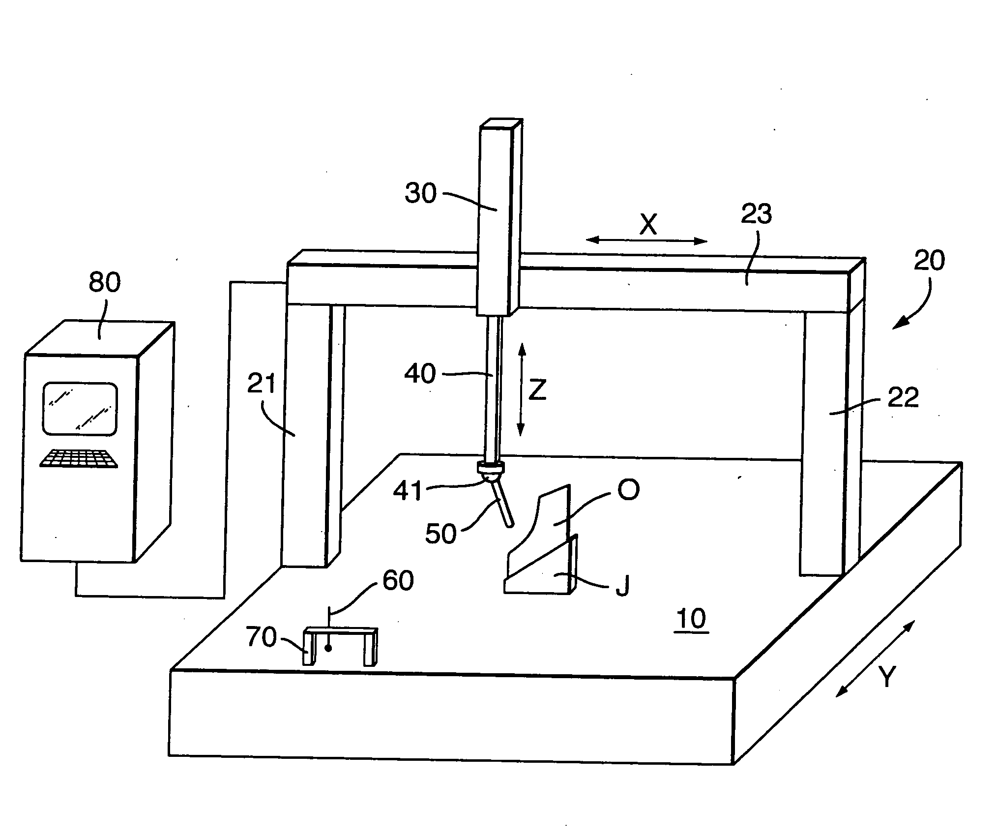
[0036]FIG. 1 shows schematically an apparatus according to the present invention. The apparatus comprises a conventional CMM which includes a table 10 on which an object O to be measured is supported. In the drawing of FIG. 1, the object is a hollow titanium alloy fan blade held in a jig J.

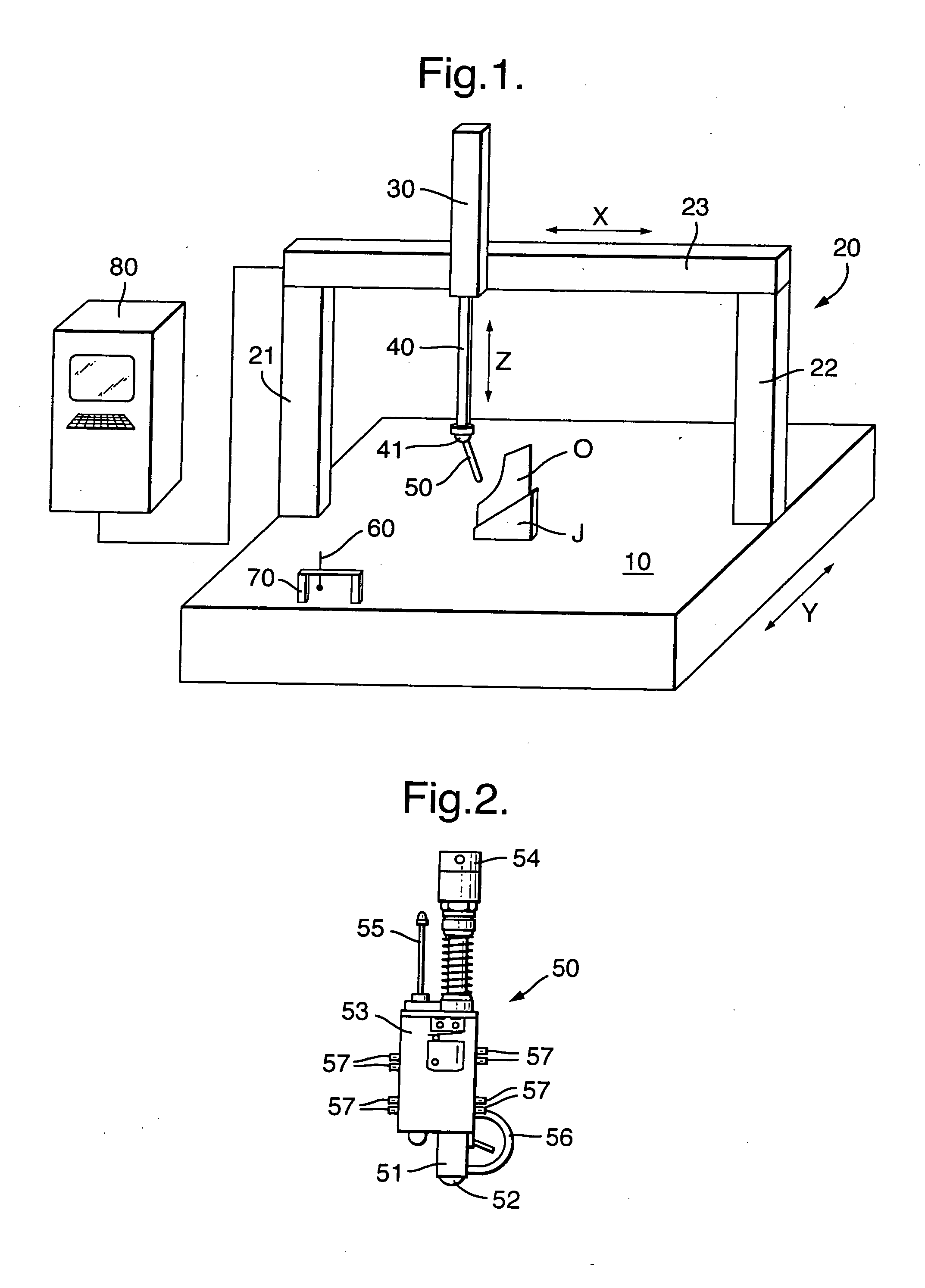
[0037]The CMM has a Y-slider device 20 which is movable in the “Y” direction of the table. The Y-slider device has columns 21, 22 at opposing sides of the table which support a beam 23 traversing the table. On the beam, an X-slider device 30 is mounted which is movable in the “X” direction of the table. The X-slider device in turn contains a quill 40 which is movable in the “Z” direction of the table. The lower end of the quill has a head 41 which can detachably hold a measuring probe and provides angular movement of the probe about two orthogonal axes. The measuring probe can be either an ultrasonic test probe 50, or a coordinate measuring stylus 60. As shown in FIG. 1, the ultrasonic test probe ...


PUM

PropertyMeasurementUnit
thicknessesaaaaaaaaaa
ultrasonic testaaaaaaaaaa
thicknessaaaaaaaaaa

Abstract

An apparatus for measuring wall thicknesses of objects, comprises: a coordinate measuring machine comprising a probe holder and an object support, the coordinate measuring machine being configured to provide relative movement between the probe holder and the object support in three dimensions; and an ultrasonic test probe which is held by the probe holder. The coordinate measuring machine brings the transducer of the ultrasonic test probe into contact with a position on a surface of an object at the object support so that the probe can measure an object wall thickness at the probe contact position.

Description

FIELD OF THE INVENTION[0001]The present invention relates to an apparatus for measuring wall thicknesses of objects, and particularly, but not exclusively, to an apparatus in which the measured wall thicknesses can be converted to spatial coordinates on surfaces of objects.BACKGROUND OF THE INVENTION[0002]Manufactured objects often have to conform to dimensional and / or geometrical tolerances. These may be specified by the manufacturer or ultimate user of the object e.g. to ensure that the object behaves correctly in service. Thus it is common to subject objects to post-manufacture inspection procedures.[0003]A known technique for determining the dimensional accuracy of objects involves driving a coordinate measuring probe or stylus over the surface of the object. Such a probe typically comprises a stiff elongate member (formed e.g. of carbon fibre) having a small hard (typically industrial ruby) sphere at the measuring end. An example of a commercially available probe is the Renisha...

Claims


Application Information

Patent Timeline
Patent Type & Authority Applications(United States)
IPC IPC(8): G01N29/24G01B5/008G01B17/02G01B21/04
CPCG01B21/04G01B17/02
Inventor HOUGH, GERALD WORCHARD, NICHOLAS BWHITESIDE, DEAN S R
Owner ROLLS ROYCE PLC
Why Eureka
Try Eureka