Air-Suction-Noise Reduction Device and Working Machine With the Same

Inactive Publication Date: 2009-07-16
KOMATSU LTD
View PDF13 Cites 14 Cited by
  • Summary
  • Abstract
  • Description
  • Claims
  • Application Information

AI Technical Summary

Benefits of technology

[0015]In the above air suction noise reduction device, it is preferable that the engine hood includes a top plate portion and side plate portions which are provided on both side edges of the top plate portion, and the reinforcing plate is arranged so as to reinforce a portion between the top plate portion and the side plate portions. Accordingly, the reinforcing plate effectively defines a space in the engine portion and effectively reinforces the engine hood.
[0016]In the above air suction noise reduction device, it is preferable that the reinforcing p

Problems solved by technology

This makes a structure of the air suction noise reduction device complicated and a space for

Method used


Image

  • Air-Suction-Noise Reduction Device and Working Machine With the Same
  • Air-Suction-Noise Reduction Device and Working Machine With the Same
  • Air-Suction-Noise Reduction Device and Working Machine With the Same

Examples


Embodiment Construction

[0025]One embodiment of the present invention will be described with reference to the drawings.

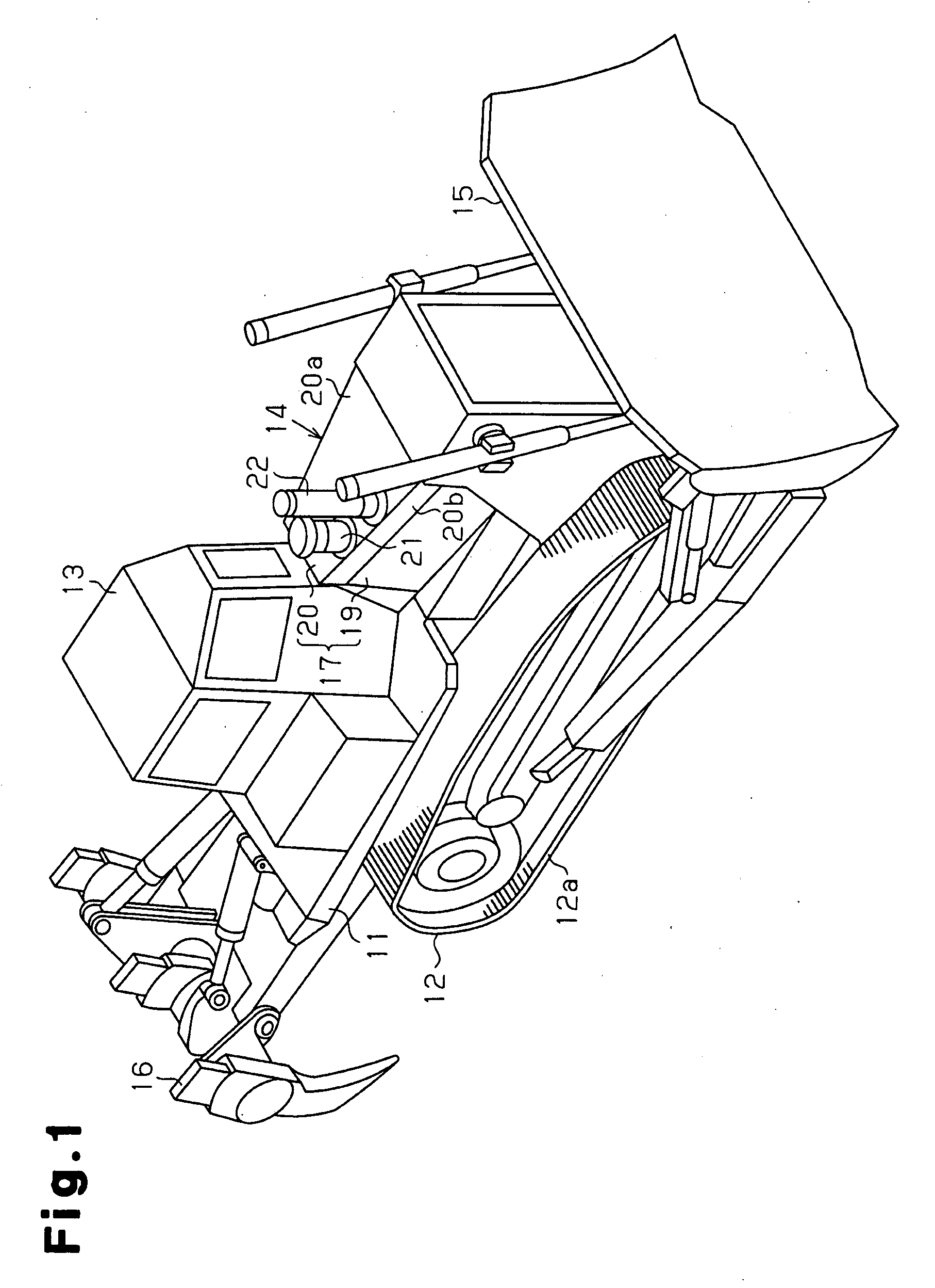
[0026]As shown in FIG. 1, a bulldozer, which is a work machine, has a frame 11. A travel unit 12 including a continuous track 12a is provided under the frame 11. A cab 13 and an engine portion 14 are provided on the frame 11. Work implements 15, 16 such as a bulldozing blade or a ripper are provided on a front portion and a rear portion of the frame 11, respectively.

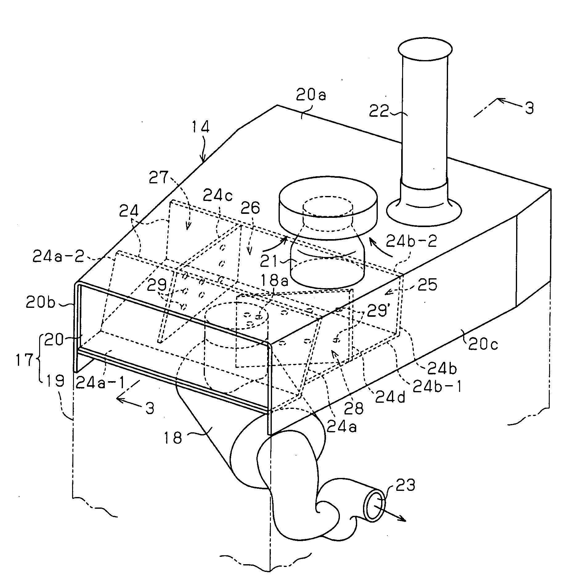
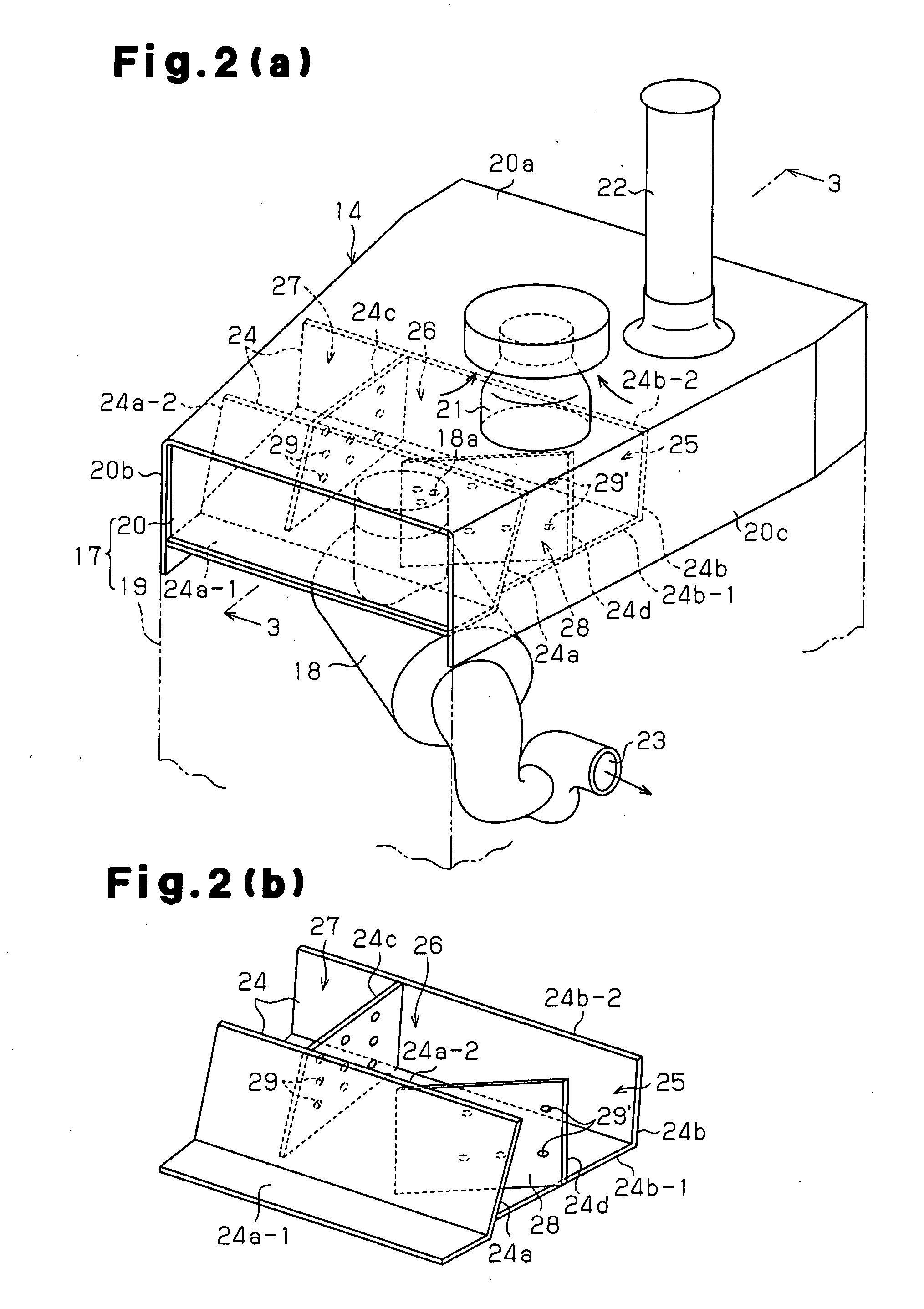
[0027]As shown in FIG. 2(a), an outer wall of the engine portion 14 is comprised of an engine cover 17. Various devices such as an engine (not shown) and an air cleaner 18 which is connected to an air intake side of the engine are accommodated in the engine portion 14. The engine cover 17 is comprised of a substantially box-shaped cover main body 19 and an engine hood 20 which is mounted to an opening portion of the upper surface of the cover main body 19. A door (not shown) for checking is provided on a side wall of the cover ...


PUM


Abstract

An engine cover 17 has a cover main body 19 and an engine hood 20 which is attached to an opening portion formed on an upper surface of the cover main body 19 and a plurality of reinforcing plates 24 are fixed to an inner surface of the engine hood 20. First to fourth reinforcing plates 24a to 24d of a plurality of reinforcing plates 24 define a space in an engine portion 14. An expansion chamber 26 which is communicated with an intake passage 23 reaching to an engine and resonant chambers 27, 28 which are communicated with the expansion chamber 26 via ports 29 are formed in the engine portion 14.

Description

FIELD OF THE INVENTION[0001]The present invention relates to an air suction noise reduction device (generally referred to as a resonator) which reduces intake noise generated at an air intake side of an engine or resonance noise which is generated in an air intake passage due to noise from an engine, and also relates to a work machine such as a bulldozer with the air suction noise reduction device.BACKGROUND OF THE INVENTION[0002]Such an air suction noise reduction device has been disclosed in Patent Document 1. In the air suction noise reduction device, an expansion chamber having a substantially box shape is provided separately from a vehicle body on an air intake passage which is connected to an engine. A resonant chamber having a substantially box shape is provided separately from the vehicle body outside of the expansion chamber. A connection port of a cylindrical shape is provided in the resonant chamber and the connection port is inserted into the expansion chamber. This conn...

Claims


Application Information

Patent Timeline
IPC IPC(8): F02M35/12
CPCB60K13/02B60Y2200/41E02F9/00E02F9/0866E02F9/0891F02M35/1277F02M35/10262F02M35/164Y02T10/146F02M35/1216F02M35/1255F02M35/10013Y02T10/12
Inventor UEMURA, ATSUSHIOKAZAWA, KOJIYABE, MITSUOIMAMURA, KAZUYAIWASAKI, MIKIONISHIMINE, SUEYOSHI
Owner KOMATSU LTD
Why Eureka
Try Eureka