Spread Spectrum Clock Interoperability Control and Inspection Circuit

a technology of interoperability control and inspection circuit, which is applied in the direction of generating/distributing signals, pulse techniques, instruments, etc., can solve problems such as the failure of products to meet the limit of radiated emission

Active Publication Date: 2009-07-16
LEXMARK INT INC
View PDF20 Cites 42 Cited by
  • Summary
  • Abstract
  • Description
  • Claims
  • Application Information

AI Technical Summary

Benefits of technology

[0011]A clock interoperability circuit is provided that can adjust subsystem SSCG clocks by use of

Problems solved by technology

If one or more of these added systems do not have an optimal SSCG pr

Method used


Image

  • Spread Spectrum Clock Interoperability Control and Inspection Circuit
  • Spread Spectrum Clock Interoperability Control and Inspection Circuit
  • Spread Spectrum Clock Interoperability Control and Inspection Circuit

Examples


second embodiment

[0049]The second charge pump 192 has its output directed to a second loop filter 194, and its output signal at 190 is the variable voltage that is directed to the analog-to-digital converter 154 in the wave shape detection circuit 150. The mask 156 is essentially equivalent to the mask 106 of FIG. 3, and the compare logic 160 is essentially equivalent to the compare logic 110 of FIG. 3. The output signal from the compare logic in FIG. 4A is at 162. Similar decisions are made by the comparison logic 160, based on the attributes of the mask 156.

third embodiment

[0050]A third embodiment is presented by using a wave shape detection circuit, generally designated by the reference numeral 155 on FIG. 4B, that replaces the ADC with a circuit that compares the wave shape at a number of predetermined profile locations or times. This comparison would be used to determine if the SSCG profile is correct for the optimum shape.

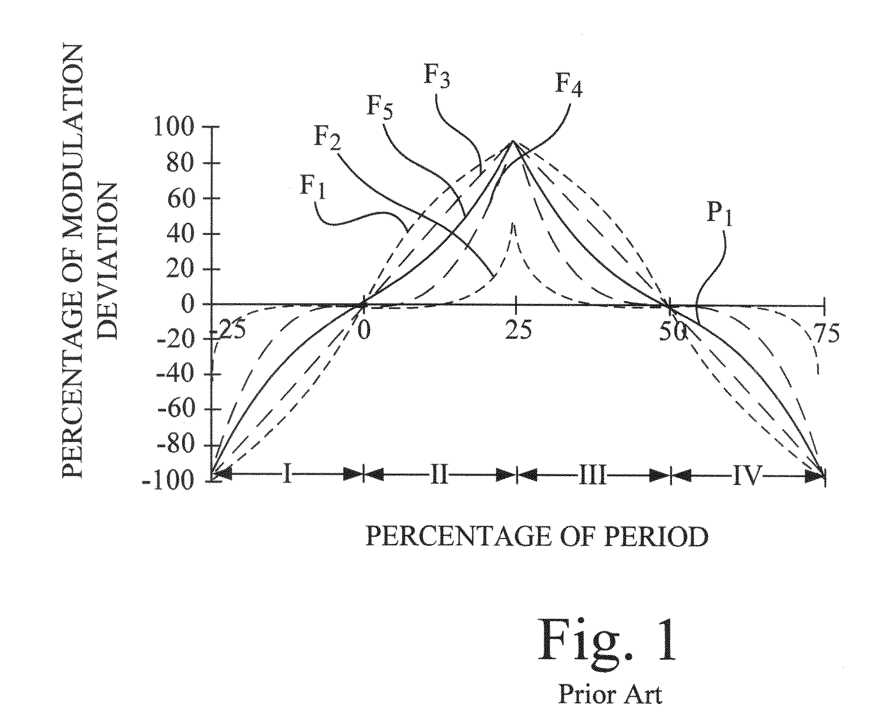
[0051]The first step is to create an analog profile to match one of the shapes found in FIG. 1 (see U.S. Pat. No. 5,488,627 column 9, line 23). The preferred shape is the F5 profile. This can be done by first creating a voltage or current triangular wave. This can be simply done by applying a constant current into a capacitor that starts at the profile average value which creates a positive ramp and continues until the positive peak. At the peak time, the sign of the current source is made negative to cause a negative ramp from that peak. This creates a triangular wave from the zero (0) deviation through the peak and back to the ...

fourth embodiment

[0056]A fourth embodiment is presented by using analog and digital circuitry to be the wave shape detection circuit to measure key aspects of the profile. The key aspects are the period, symmetry, amplitude and inflections of the profile. Referring back to FIG. 1, the period can be determine by finding the time between the zero (0) deviation crossings and adding the positive deviation half period to the negative deviation half period.

[0057]The fourth embodiment is depicted in FIG. 5, which shows a circuit 200 that can be used to determine the positive and negative ½ periods of the modulation waveform; these added together result in the modulation period. Symmetry can be checked by comparing the one-half period values that should be close to the same value if the area above and below the average is the same.

[0058]In the circuit 200, a demodulation circuit 210 sends a signal to a low pass filter 212 and also to a pair of comparators 220 and 224. The low pass filter 212 also outputs a ...


PUM


Abstract

A spread spectrum clock generator (SSCG) control and inspection circuit provides a system and method for inspecting and controlling an external SSCG, and for verifying the modulation profile waveform of an external SSCG. An electronic circuit is included that can check for the presence of an optimal SSCG modulation profile in product subsystems, and in attached modular systems, including electronic plug-in features such as internal network adapters and cartridges. In one mode of the invention, an electronic circuit ensures continued radiated emissions compliance for field replaceable units or consumable parts within a product, such as a printer, a scanner, or a combination (or all-in-one) printer/scanner. In another mode of the invention, an electronic circuit may also act as a secondary security device for consumable products, such as toner cartridges or ink jet cartridges. In yet another mode of the invention, an electronic circuit may also adjust the attached SSCG clock.

Description

STATEMENT REGARDING FEDERALLY SPONSORED RESEARCH OR DEVELOPMENT[0001]None.REFERENCE TO SEQUENTIAL LISTING, ETC.[0002]None.BACKGROUND[0003]1. Field of the Invention[0004]The present invention relates to spread spectrum clock generator (SSCG) circuits, and more particularly provides a system and method for inspecting and controlling an external spread spectrum clock generator, and for verifying the modulation profile waveform of an external spread spectrum clock generator. The invention includes an electronic circuit that has the ability to check for the presence of an optimal or “Lexmark” SSCG modulation profile in product subsystems, and in attached modular systems, including electronic plug-in features such as internal network adapters and cartridges. In one mode of the invention, an electronic circuit ensures continued radiated emissions compliance for field replaceable units or consumable parts within a product, such as a printer, a scanner, or a combination (or all-in-one) print...

Claims


Application Information

Patent Timeline
IPC IPC(8): H03K5/01
CPCB41J2/17546G06F21/725H03K5/082H03K3/84G06F2221/2129
Inventor HARDIN, KEITH BRYANOGLESBEE, ROBERT AARON
Owner LEXMARK INT INC
Why Eureka
Try Eureka