Multi-parallel magnetic-field cancellation type transformer

a transformer and magnetic field technology, applied in the direction of transformer/inductance, fixed transformer, transformer/inductance core, etc., can solve the problem that the conventional dc-dc converter cannot smooth out the pulsation (variation) of ripple current without increasing, the size of passive elements such as capacitors and inductors cannot be reduced and the size of the dc-dc converter is difficult to reduce, so as to prevent the damage of the electric power conversion circuit, reduce the size of the core loss

Active Publication Date: 2009-07-16
HONDA MOTOR CO LTD
View PDF6 Cites 20 Cited by
  • Summary
  • Abstract
  • Description
  • Claims
  • Application Information

AI Technical Summary

Benefits of technology

[0043]Accordingly, the switching element including the flywheel diode can prevent damage to the electric power conversion circuit by providing a path of the current when an inductor is turned off. Accordingly, the electric power conversion circuit allows the current to flow in both directions.
[0044]Accordingly, if the coils disposed in parallel increase in number, the transformers of the present invention can prevent magnetic saturation of the core and reduce the size thereof and a core loss. Consequently, the electric power conversion circuit can reduce the size thereof and improve the electric power conversion efficiency.
[0045]Further, the transformers of the present invention can reduce the current flowing through each coil, and prevent the core loss generated in the core and the deterioration of electric power conversion efficiency.

Problems solved by technology

Accordingly, the conventional DC-DC converter cannot smooth out the pulsation (variation) of the ripple current without increasing the body dimension (size) of a capacitor or an inductor.
Therefore, it is difficult to reduce the size of such passive elements as capacitors and inductors and reduce the size of the DC-DC converter disclosed in JP2006-149054.
Further, according to the conventional DC-DC converter, when the step-up / down rate is equal to or greater than two times, an increase of the ripple current leads to the deterioration of electric power conversion efficiency.

Method used


Image

  • Multi-parallel magnetic-field cancellation type transformer
  • Multi-parallel magnetic-field cancellation type transformer
  • Multi-parallel magnetic-field cancellation type transformer

Examples


Embodiment Construction

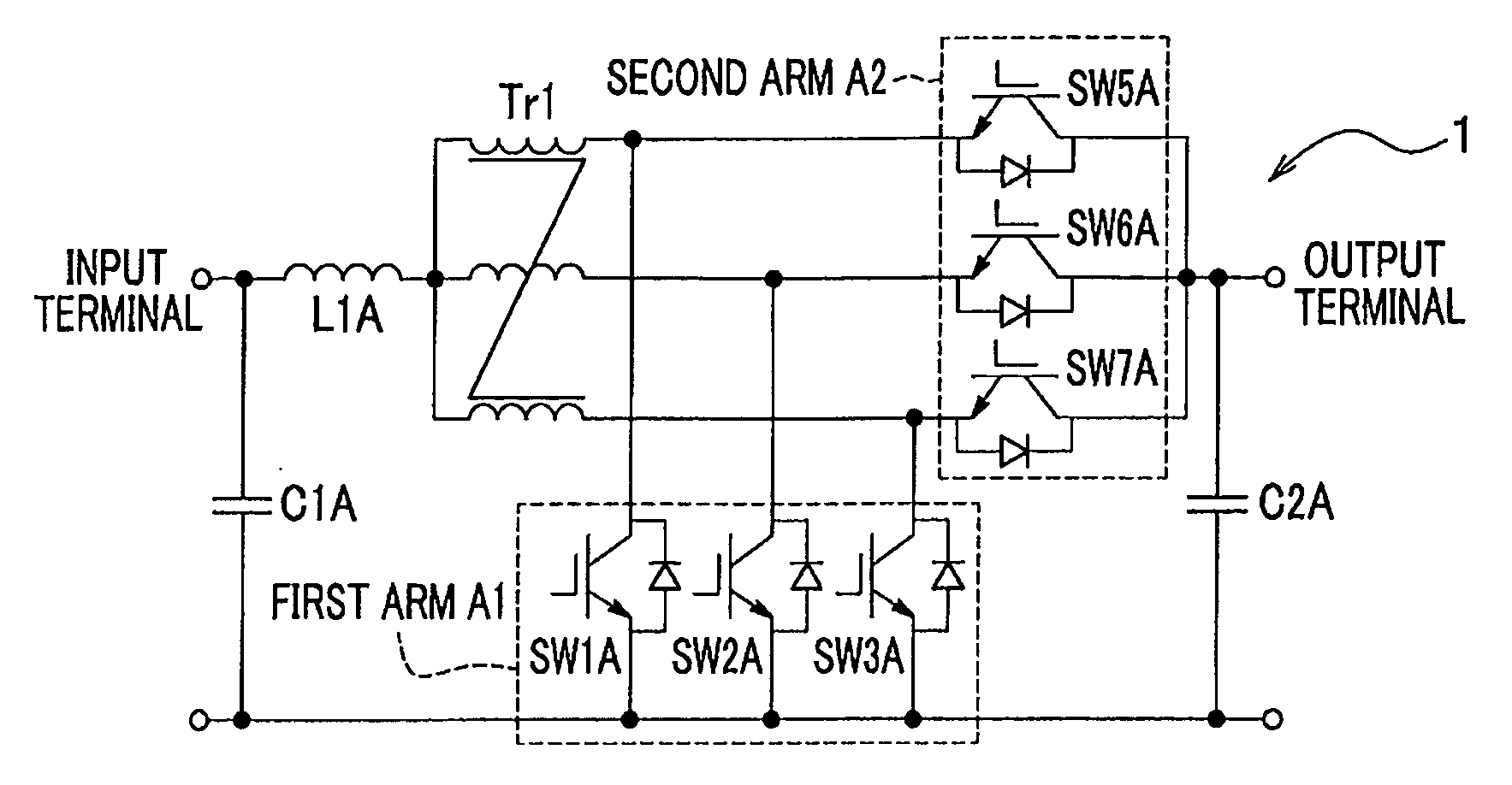
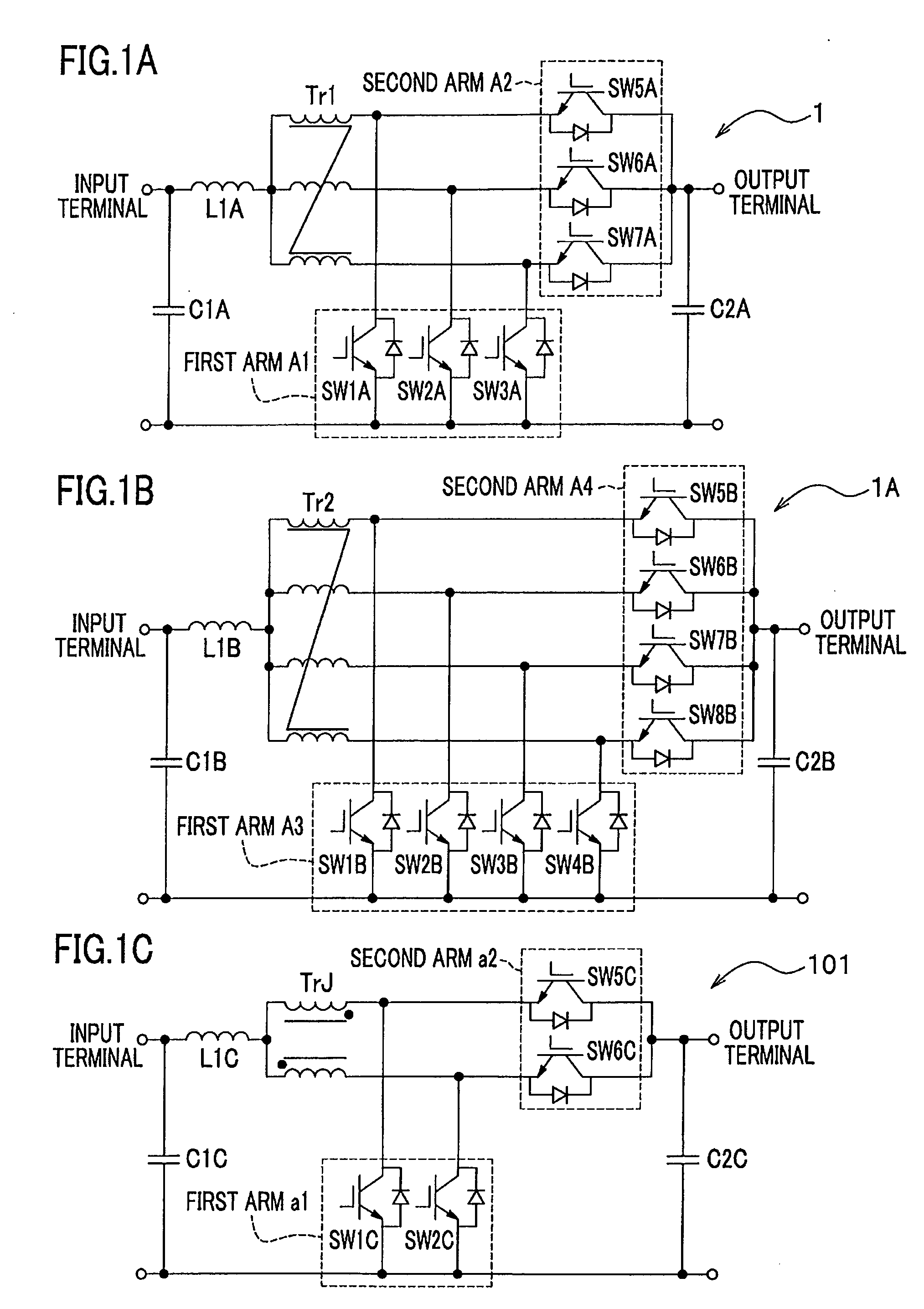
[0056]Next, embodiments of the present invention will be described with reference to drawings in detail. FIGS. 1A and 1B are a circuit diagram of an electric power conversion circuit. The electric power conversion circuit of FIG. 1A includes a three-parallel magnetic-field cancellation type transformer. The electric power conversion circuit of FIG. 1B includes a four-parallel magnetic-field cancellation type transformer. An electric power conversion circuit of FIG. 1C includes a conventional two-parallel magnetic-field cancellation type transformer. Hereinafter, the operation of the electric power conversion circuit of the present invention will be described, compared with the operation of the conventional electric power conversion circuit whose description is schematically shown.

[0057]FIG. 1A shows an electric power conversion circuit 1, wherein, in voltage step-up operation, a voltage applied to an input terminal (first input / output connecting terminal) is stepped up and supplied ...


PUM

PropertyMeasurementUnit
currentaaaaaaaaaa
electric currentaaaaaaaaaa
ripple currentaaaaaaaaaa

Abstract

A multi-parallel magnetic-filed cancellation type transformer includes a plurality of coils which generate magnetic flux during energization and a core having a plurality of magnetic leg portions on which the coils are wound, and bases for fixing the magnetic leg portions. The plurality of coils are wound on the magnetic leg portions in such a manner that the magnetic flux generated from the coils are formed in the directions opposite to each other. A plurality of closed magnetic circuits of the magnetic flux are formed at the magnetic leg portions and the bases. The magnetic resistance of the closed magnetic circuits is homogeneous. Accordingly, the transformer can reduce the size thereof, and prevent the deterioration of electric power conversion efficiency.

Description

CROSS-REFERENCE TO RELATED APPLICATION(S)[0001]This application claims the foreign priority benefit under Title 35, United States Code, § 119 (V1)-(d), of Japanese Patent Application No. 2008-006438A, filed on Jan. 16, 2008 in the Japan Patent Office, the disclosure of which is herein incorporated by reference in its entirety.BACKGROUND OF THE INVENTION[0002]1. Field of the Invention[0003]The present invention relates to a multi-parallel magnetic-field cancellation type transformer for converting a voltage and an electric power conversion circuit including the transformer.[0004]2. Description of the Related Art[0005]Heretofore, there is known an electric power conversion circuit, a so-called DC-DC converter, which converts electric power by stepping up / down an input voltage (for example, JP2006-149054A discloses the DC-DC converter).[0006]The conventional DC-DC converter disclosed in JP2006-149054A includes a transformer in which a primary coil and a secondary coil are connected to ...

Claims


Application Information

Patent Timeline
Patent Type & Authority Applications(United States)
IPC IPC(8): H02M7/00H01F19/00
CPCH01F27/385H02M3/1584H01F37/00H01F30/12H02M1/0064
Inventor HASHINO, SATOSHINAGANO, MASAOHIRAKAWA, MITSUAKI
Owner HONDA MOTOR CO LTD
Why Eureka
Try Eureka