

Closable loop access guide catheter
- Summary
- Abstract
- Description
- Claims
- Application Information
AI Technical Summary
Benefits of technology
Problems solved by technology
Method used
Image

Examples
Embodiment Construction
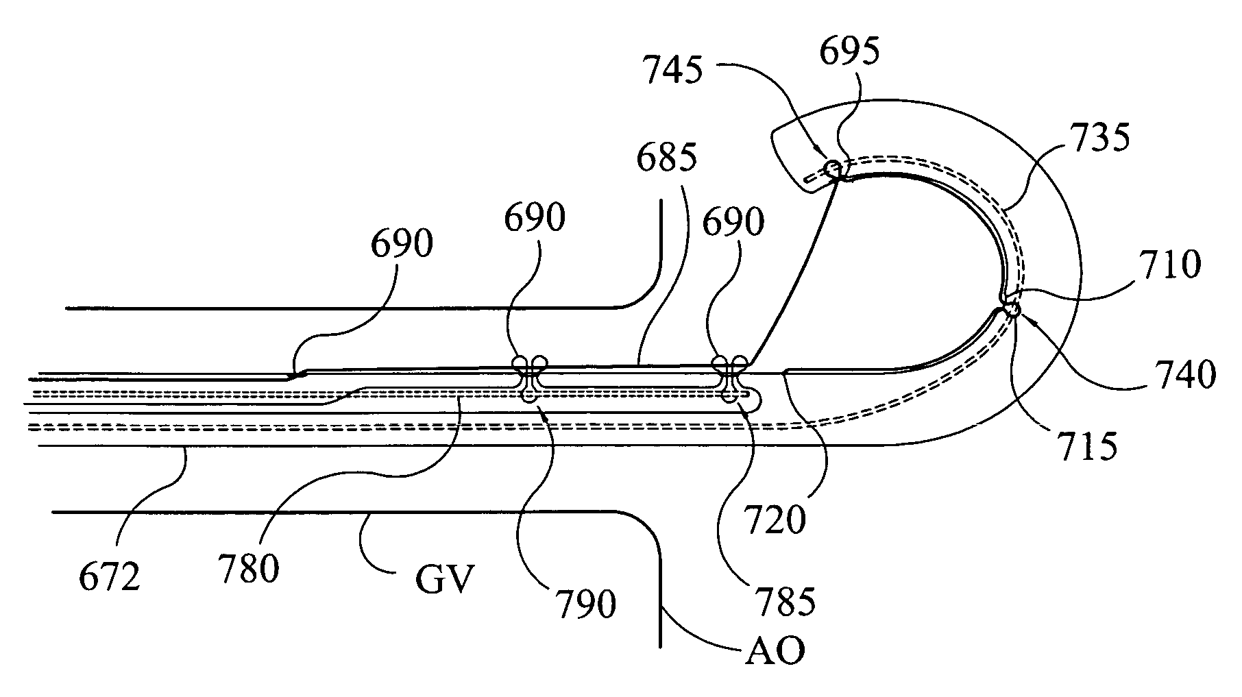
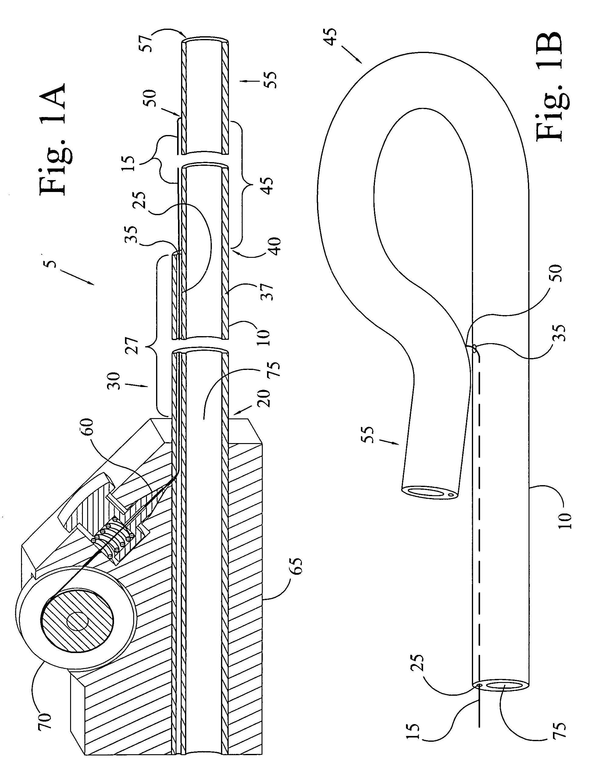
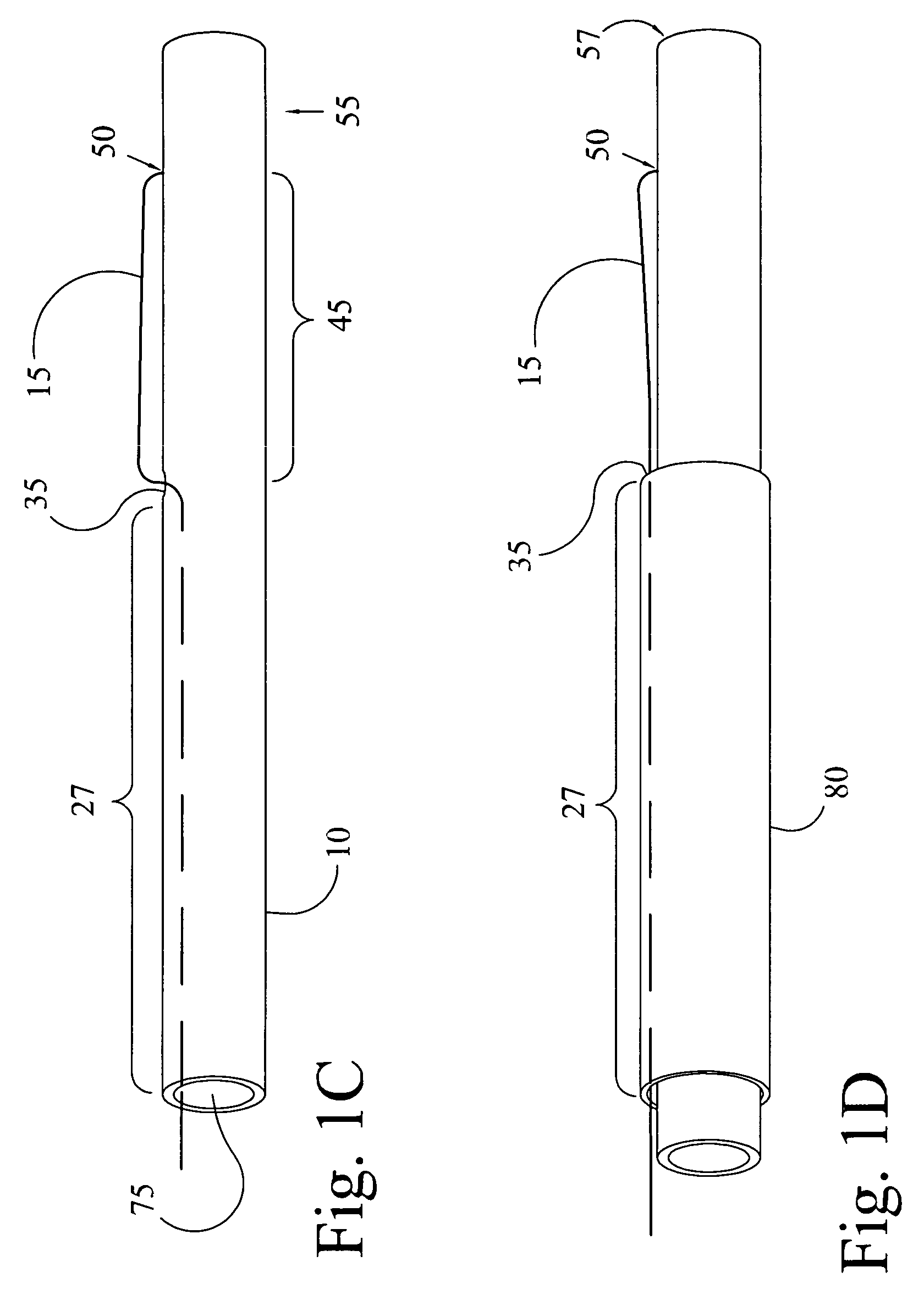
[0065]The present invention is an access guide catheter that is low profile to allow access via a radial artery approach and provides support for passage of an interventional catheter such as a stent system by forming a closed loop conformation. Larger catheters can also be formed using the present invention for other tubular vessels and applications not limited by vessel size. The low profile is accomplished by providing a very thin fiber that attaches near the distal region of the catheter and forces it to form a closed loop in the loop region of the catheter but still provide a great deal of support even though the wall thickness is thin and flexible. Support is provided by the closed loop which does not open up or back out of an ostium as tension is applied to the access guide catheter and an interventional catheter is being advanced within it.
[0066]FIG. 1A shows one embodiment of the access guide catheter (5) of the present invention. It is a 5-6F catheter intended to fit well ...
PUM
 Abstract
Description
Claims
Application Information