Expandable guide sheath and apparatus and methods for using such sheaths

Active Publication Date: 2009-07-16
MEDTRONIC INC
View PDF55 Cites 39 Cited by
  • Summary
  • Abstract
  • Description
  • Claims
  • Application Information

AI Technical Summary

Benefits of technology

[0020]Upon completing the procedure, the sheath may be removed from the body lumen. Optionally, the sheath may be at least partially collapsed from the enlarged condition before removing the sheath from the body lumen, e.g., by creating a vacuum within the sheath and/or by withdrawing the sheath into a catheter or other tubular member. Alternatively, the sheath may be split along a single longitudinal seam, or along two or more seams into two or more pieces to facilitate removal from the body lumen.
[0021]Thus, a sheath in accordance with the present invention may provide a primary access device that is substantially flexible, collapsible, and/or compliant. This primary device may assume a relatively low profile to facilitate advancement through narrow passages and/or tortuous anatomy, e.g., into difficult to access locations deep within a patient's body. Once a desired location is reached, the primary device may be released and/or expanded, and one or more secondary device(s) may be advanced through the primary device. The primary device may provide a lubricious path, prevent dissection of a vessel wall, and/or otherwise facilitate delivering the secondary device(s) into difficult to access locations. The primary device may be free to expand to accommodate the secondary device(s) and/or to substantially translate axial forces, e.g., caused by pushing the secondary device(s), into radial forces, thereby minimizing risk of damage to the passages through which the secondary device(s

Problems solved by technology

There are many risks involved with advancing instruments over a guidewire.
For example, a catheter or other instrument may skive or otherwise damage a wall of a vessel, particularly as the instrument passes through narrow passages or tortuous anatomy involving sharp bends.
Such instruments also risk dis

Method used


Image

  • Expandable guide sheath and apparatus and methods for using such sheaths
  • Expandable guide sheath and apparatus and methods for using such sheaths
  • Expandable guide sheath and apparatus and methods for using such sheaths

Examples


Embodiment Construction

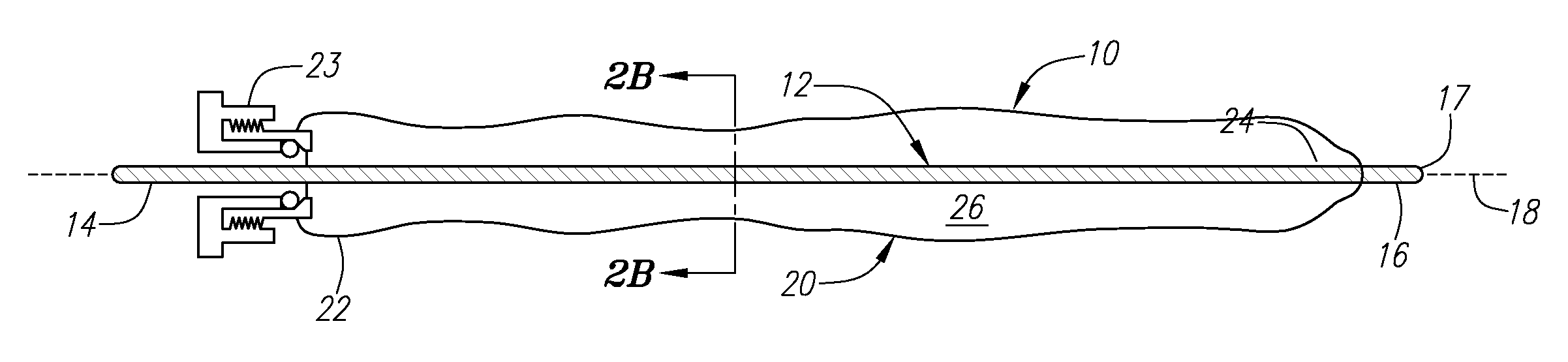
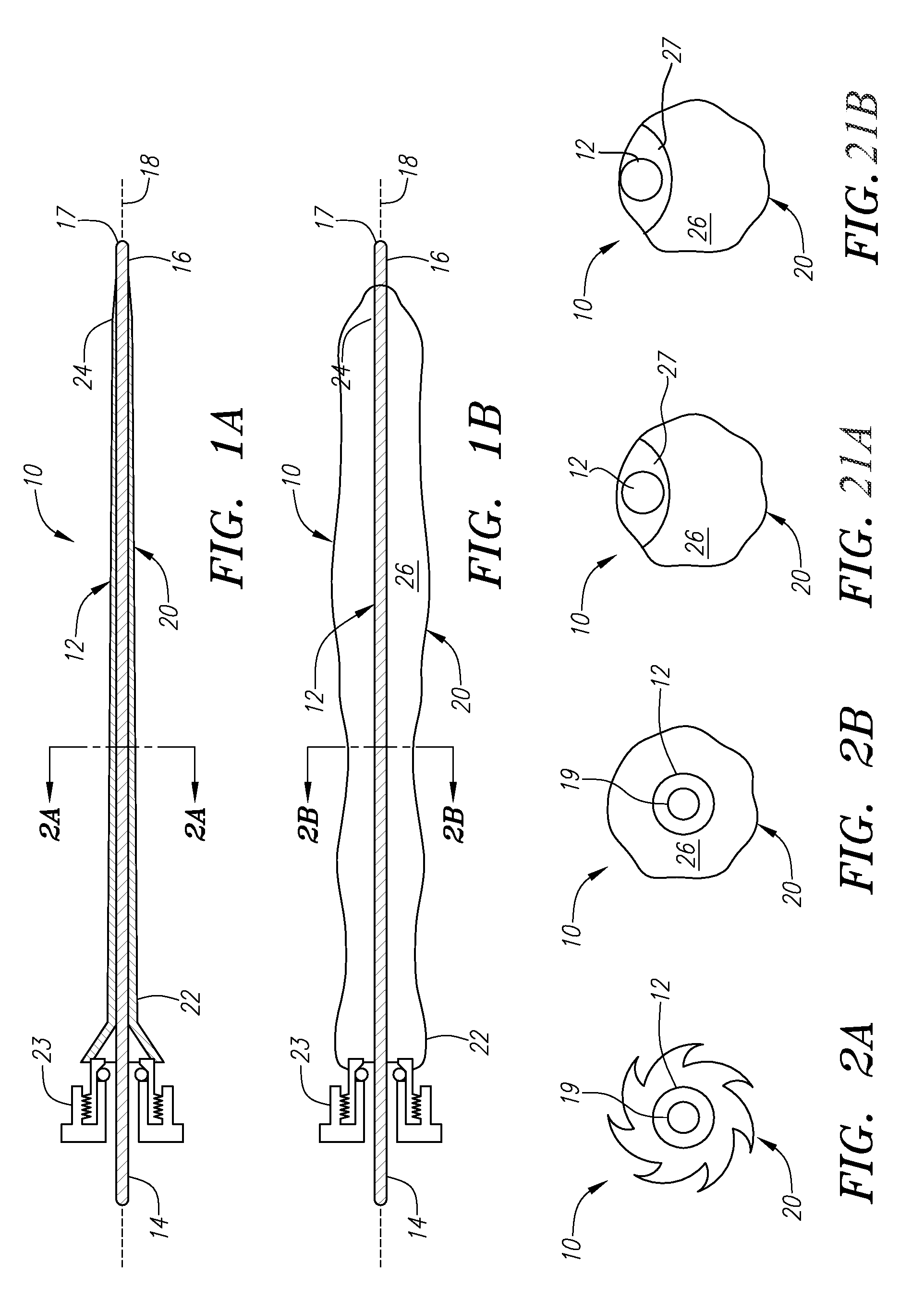
[0048]Turning to the drawings, FIGS. 1A-2B show a first preferred embodiment of an apparatus 10 for providing access within a body lumen (not shown) and / or for delivering one or more instruments (also not shown) within a body lumen, such as a vessel within a patient's vasculature, a passage within a patient's gastrointestinal tract, urogenital tract, respiratory tract, lymphatic system, and the like.

[0049]Generally, the apparatus 10 includes a flexible elongate stiffening member 12 providing a “backbone” for the apparatus 10, and an expandable membrane or sheath 20. The stiffening member 12 includes a proximal end 14 and a distal end 16 defining a longitudinal axis 18 therebetween. In addition, the stiffening member 12 may have sufficient length to be advanced from a location outside a patient's body (not shown) through any intervening body passages into a site to be accessed and / or treated. The distal end 16 may have a size and / or shape for insertion into a body lumen, e.g., includ...


PUM


Abstract

Apparatus and methods are provided for accessing body lumens and/or for delivering instruments into body lumens, e.g., vessels within a patient's vasculature. A flexible sheath is provided that is expandable from a contracted condition to an enlarged condition wherein the sheath at least partially defines a lumen therein. The sheath is lubricious and has a relatively thin wall, thereby providing a collapsible/expandable guide for delivering fluids and/or instruments through tortuous anatomy and/or into relatively narrow passages. The sheath is advanced from an entry site to a body lumen in the contracted condition. Once the sheath reaches a target body lumen, the sheath is expanded to the enlarged condition, thereby defining a lumen within the sheath, and fluids and/or instruments are introduced into the body lumen via the sheath lumen. Upon completing the procedure, the sheath is removed from the body lumen.

Description

[0001]This application is a continuation of co-pending application Ser. No. 10 / 423,321, filed Apr. 24, 2003 which claims benefit of provisional application Ser. No. 60 / 376,065, filed Apr. 25, 2002, the disclosure of which is expressly incorporated herein by reference.FIELD OF THE INVENTION[0002]The present invention relates generally to apparatus and methods for delivering instruments and / or agents during a medical procedure, and, more particularly, to guide sheaths for accessing body lumens and / or delivering instruments into body lumens of a patient.BACKGROUND[0003]Minimally invasive procedures have been implemented in a variety of medical settings, e.g., for vascular interventions, such as angioplasty, stenting, embolic protection, electrical heart stimulation, heart mapping and visualization, and the like. These procedures generally rely on accurately navigating and placing instruments within a patient's vasculature.[0004]During such procedures, a target vessel may be accessed us...

Claims


Application Information

Patent Timeline
IPC IPC(8): A61M25/01A61B17/34A61F2/01A61F2/06A61F2/84A61M25/06A61M25/10A61M29/02
CPCA61B17/3431A61M2029/025A61F2/95A61F2002/011A61F2002/9511A61M25/0662A61M25/0668A61M25/1002A61M25/1027A61M25/104A61M2025/0177A61M2025/0681A61M2025/1004A61M2025/1088A61B17/3439A61F2/011
Inventor EVERSULL, CHRISTIAN SCOTTMOURLAS, NICHOLAS J.LEEFLANG, STEPHEN ARIENAYAK, ASHA SHRINIVASMILLER, DAVID JOHN
Owner MEDTRONIC INC
Why Eureka
Try Eureka